After the difficulties with the first few flights, I thoroughly enjoyed flying the LA Rotorshape so, when the plan for the Panther autogyro was published in the April 2013 edition of RCM&E magazine, I fancied giving it a go. A few days later I crashed the Rotorshape (the dreaded disorientation problem) and, although it was repairable, I took this as a signal that it was time to move on so decomissioned the Rotorshape and started drawing up a shopping list for the Panther build.
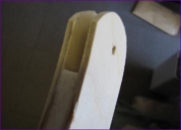
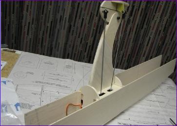
April 2013 With the essential bits to hand, the plan was laid out and, as recommended in the magazine article, I started with the rotor mast. This is built from a 1/4in balsa core, with 1/8in balsa laminations on either side, making sure that the grain runs in different directions on all three pieces for maximum strength. Before fitting the laminations, two 4mm bolts were epoxied into ply inserts in the bottom of the central core. These will go through the bottom of the fuselage, making the mast assembly removeable as a unit. The reasons for this design feature become clear shortly.
Two 1/8in ply 'tongues' are also fitted at the top of the mast. These will take the pitch pivot bolt for the rotorhead.
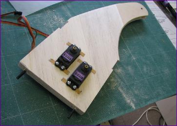
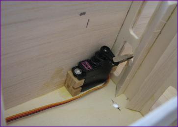
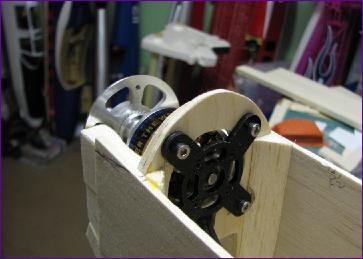
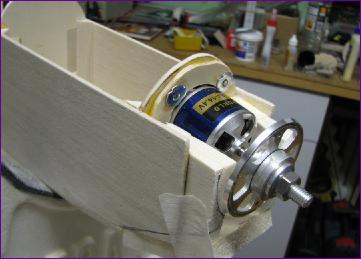
I have been using Hitec HS81, 82 or 85 metal geared servos for many years now and always found them to be more than adequate, even on quite large models so when I saw that the servo recommendation for the Panther was not only for full size servos, but for high torque digital ones at that, I was a bit sceptical. However it seems that the rotor tilt servos do have to deal with some heavy loads as they effectively swing the body of the aircraft about, almost like weight shift control in a hang glider. Reports also came in of a few instances of strange handling characteristics being traced to weak servos so I followed the designer's recommendation and fitted TowerPro MG996R 10kg.cm digital servos to the mast.
With the servo fitting sorted, a few liteply pieces were added to the mast which will locate into the fuselage.
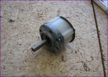
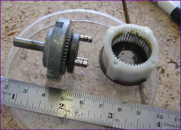
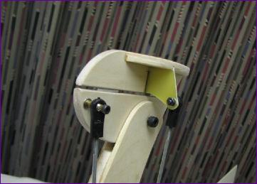
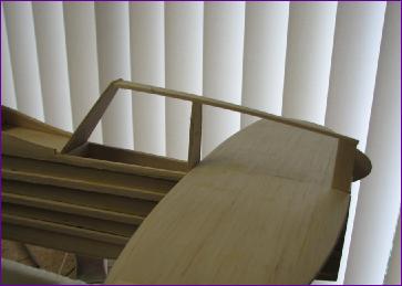
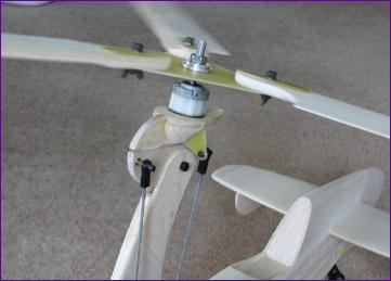
Next, I embarked on the head assembly. Rather than fabricate a bearing assembly, I dug out the front end of a Robbe Planeta gearbox, which had done eight years service on the front of a Speed 700 motor in my Stearman before its brushless update. With the planet gears removed, the shaft spins nice and freely, so hopefully it will be good for another eight years!
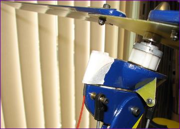
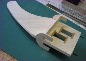
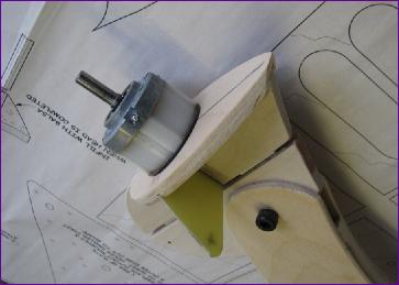
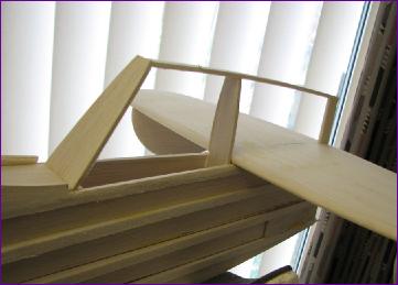
Of course, the spindle has to be tilted for both roll and pitch. The pictures below show how this is achieved on the Panther - simple, but very solid.
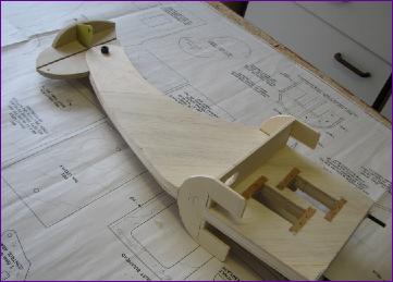
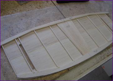
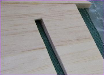
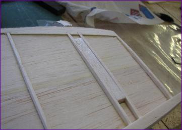
Fuselage construction starts by building the mid section to accommodate the slide-in mast unit.
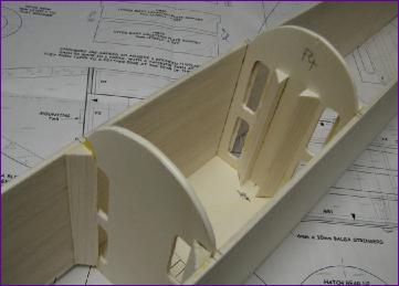
Of course, I couldn't resist sorting out the linkages so that I could see the rotor tilt mechanism in action!
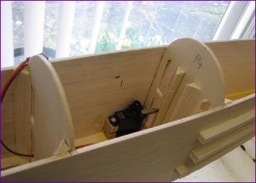
The plan suggests mounting the rudder servo behind the mast bay but, after a bit of awkward measuring, I managed to convince myself that the servo could be squeezed in behind the roll and pitch servos, so avoiding the need for another access hatch.
I opted for a built up tailplane rather than the solid 1/4in sheet shown in the plan. One benefit of this is that it was easy to let the subfins into the structure, whilst leaving the top skin intact.
Rather than sheet in the turtle deck, leaving a slot for the tailplane to slide in, I opted to fit the tailplane before the sheeting. I'll probably pay the price in terms of hangar rash, but it just seemed easier that way.
I departed a bit from the plan at the front end too. To avoid the need for a detachable cowling, the firewall was moved forwards and a large hole cut so that the motor can be inserted and removed from the battery bay. Once the spinner position was noted, the front end was built up with balsa block, the top section being planked with 3/32in balsa.
Last step on the fuselage was to make the battery hatch cover. So, one month in, there is just the blades, spats and covering to go. . . .
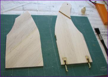
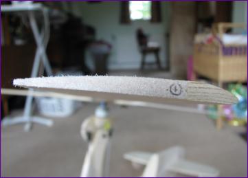
May 2013 The blades are made from 3/4" x 1/4" pine for the leading edge, backed by 1/4in balsa. Some people made elaborate sanding jigs or used a belt sander. I settled for hand sanding with Permagrit blocks, guided by a ply template, although I have to confess to abandoning the template in the end and doing the final shaping by eye.
This shows the blade section. The Pine was bought from B&Q and was a fairly mean 6mm thick so my blades are a bit thinner than specified. This picture also shows a somewhat flattened upper surface where the balsa was sanded down to align with the pine. It was issues like this which limited the usefulness of the template.
Once the sanding was done, the blades were balanced in pairs by adding Balsaloc prior to covering. I made four blades from the same sheet of balsa but one of them turned out a bit heavier than the others so was put aside fairly early on. As the Balsaloc was added, the spanwise cg of the blades was monitored to try to get the three blades as closely matched as possible. Once the reinforcing plates had been added at the root, the bolt holes were drilled on the chordwise cg and the blades balanced again before covering. To avoid wear and tear on the nyloc nuts, the blades were temporarily fitted to the head with wing nuts for these pictures.
The spats were made from balsa with 1/16in ply sides, secured to the axles with double armed nosewheel steering arms. Unfortunately, I don't seem to have taken any pictures of them under construction. Then it was out with the covering iron.
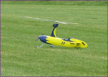
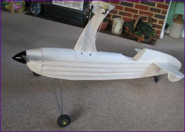
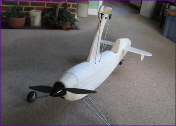
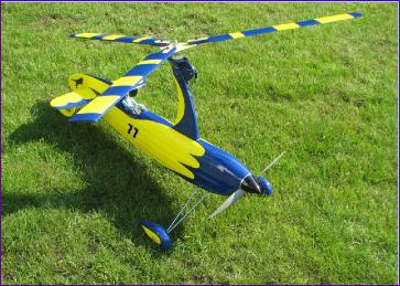
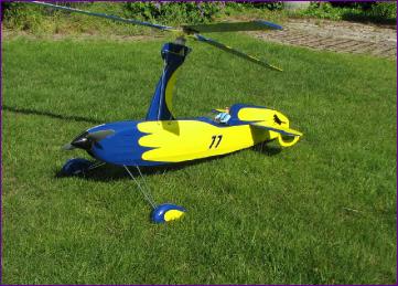
June 2013 Before long the various parts were all covered, and it was time to put it all together one more time.
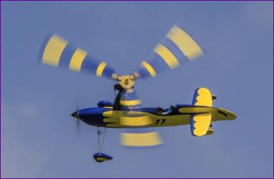
The blades are striped on the top (mathematicians might spot a nod to Fibonacci there!) and plain dark blue underneath, as an orientation aid. The overlaps of the stripes provided a last opportunity to fine tune the blade balance. Panther and number decals are from Tim at Model Markings.
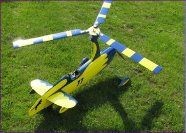
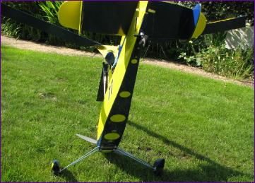
Having crashed a couple of rotary winged craft due to disorientation, I thought hard about what I could do do help with this problem. As well as the blades, these are the other aspects of the colour scheme dreamt up with orientation in mind:
Tailplane solid blue underside, blue/yellow on top
Spats solid blue on insides, blue/yellow outside
Subfins solid blue on insides, yellow outside.
Yellow cirles on underside of fuselage.
Time will tell whether it all helps!
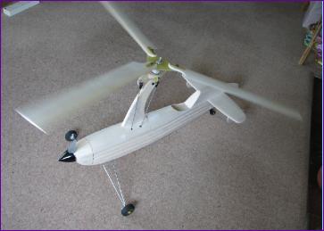
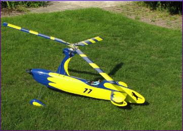
With the Panther sitting on the grass, pointed into wind, the blades seemed eager to spin up and there was no vibration, suggesting that the blades were well balanced. However, the weather then took a turn for the worse so, whilst waiting for a suitable break for the maiden flight, I set about sorting out the storage arrangements for the Panther - always an issue in my ever more crowded workshop cum model hangar.
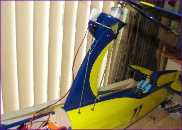
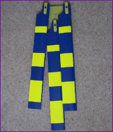
I had hoped to leave the blades attached and support them over the rear fuselage with a caddy of some sort . However, as you can see from this picture, unlike helicopter blades, these do not fold neatly over the top of each other so that option wasn't really practicable. Instead, the complete head was removed and hung on a screw on the side of a cupboard.
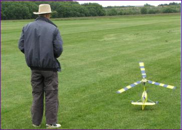
Eventually, the wind abated, and it was off to the flying field.
The grass at the field had just been mown but was very lush and thick. This posed a problem, in that the spatted wheels seem to sink without trace and all the Panther wanted to do was nose over (as you can see on the video clip). All the advice is to make a steady, protracted take-off run to give the rotors plenty of time to get up to speed before attempting to lift off. However, all I could do was pulse the throttle until the spats started to drag trhough the grass, apply full back stick to try to prevent the nose over, and hang on!
On this first flying outing, I was having to hold in a lot of rearward rotor tilt and, in spite of taking out some noseweight for the second flight, on the landing circuit the model seemed to drop out of the sky and the Panther sustained some damage to the rear end as a result of a blade strike. Fortunately though, the blades themselves were undamaged and the repairs to the tail were fairly straightforward.
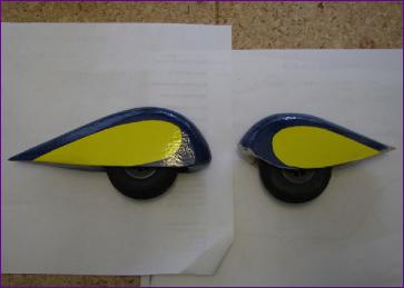
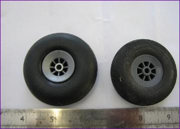
On the designer's advice, I took the 0.4mm ply negative shims out from under the blades for the second outing. The spats also underwent some surgery as you can see from the before and after picture below left. By hollowing out the spats a bit more I was also able to increase the wheel diameter by 1/4in.
While making these changes, I had plenty of time to ponder over just went wrong with that landing circuit. With fixed wing aircraft, when throttling back to descend on the downwind leg, I reckon I automatically ease the elevator stick forwards to make sure that the airspeed doesn't drop off. With an autogyro though it's head speed rather than airspeed which you need to maintain and pushing forward on the elevator will presumably decrease the rotor speed - not really noticeable while you are deliberately descending, but gets you into trouble as soon as you try to arrest the descent.
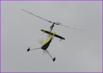
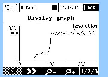
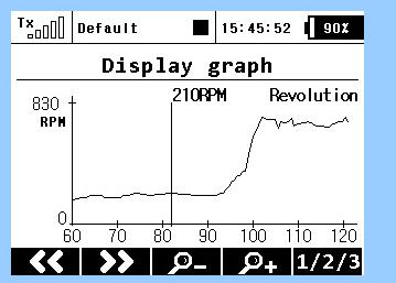
Anyway, with the shims removed, the spats re-modelled, and the pilot striving to get into autogyro mode, the second flying session went much better. Two uneventful flights were made, the need to keep hauling back on the stick had gone and there seemed to be no tendency to drop out of the turns. Encouraged by this, I temporarily fitted an rpm sensor to the mast for the next session with a view to getting a better insight into the rotor behaviour.
To avoid looking at the transmitter screen, it was set up to read out the rpm every five seconds. Of course, there is an inevitable delay in the system and the synthesised voice says "Revolutions, 200" so by the time you hear a number it's going to be a bit out of date. Nonetheless, it seemed that the rotors spun up to about 240 rpm sitting on the ground, accelerated steadily during the takeoff run and settled to around 700 - 800rpm throughout the flight. It's hard to be sure just where on that rising curve the model lifted off, but it is tempting to think that it might be around that kink just before the 100 second mark at around 350rpm.
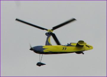
So, I am well pleased with the performance of the Panther. It is much more pleasant to fly than the Rotorshape and so hopefully will have a long and active service life. Do check the Video Clip and Slideshow links below for the latest movies and pictures.
 With the Panther sitting on the grass, pointed into wind, the blades seemed eager to spin up and there was no vibration, suggesting that the blades were well balanced. However, the weather then took a turn for the worse so, whilst waiting for a suitable break for the maiden flight, I set about sorting out the storage arrangements for the Panther - always an issue in my ever more crowded workshop cum model hangar.