It's hard to believe that my Panther has been flying for six years now. Whilst I still have to take care not to become disorientated, I've steadily become much more confident with its flying characteristics. So, when designer Richard Harris embarked on producing a pusher autogyro as a suitable follow-on model, I watched with interest. The design went through a couple of iterations resulting in a very attractive model. The beta builders reported favourably on its flying characteristics so I thought I'd give it a go.
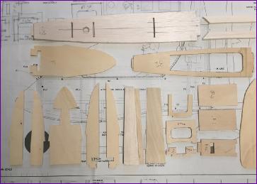
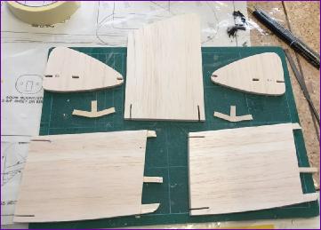
September 2019 I try not to start my 'Winter builds' before September. However, I do sometimes lay in some of the items needed such as servos, motor etc. ahead of time. This time I have to confess that, as well as buying the commercial items, I did switch on the scroll saw and cut out a number of the ply parts in the last few days of August. With a bit of trimming and sanding, they seemed to fit together pretty well.
Oh Okay, I admit it - I did get the glue pot out on the 31st August.
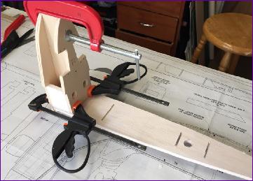
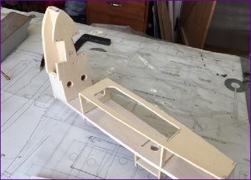
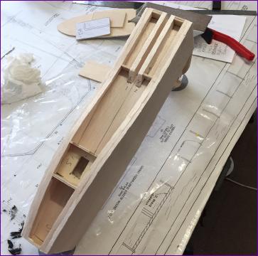
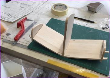
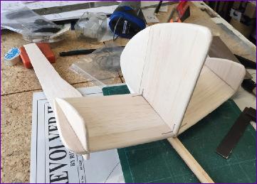
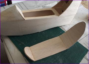
With the mast housing attached to the baseplate, the rest of the fuselage carcass builds up quickly.
The sheet sides are then added, followed by the tail boom housing. I found it easiest to fit the lower longerons after the sides were in place. Because of their curvature, I used two strips of 6mm x 3mm balsa rather than the 6mm sq. shown on the plan.
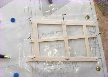
The tail surfaces are shown as 6mm Depron. I like to finish my models with film covering rather than paint where possible and Depron really doesn't take too kindly to the covering iron. Added to which, I didn't have any in stock. So instead, frames were built from 2.3mm balsa then skinned with 1.5mm balsa, resulting in a similar overall thickness.
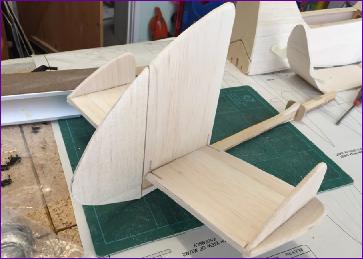
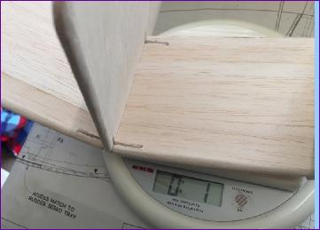
The tip sections of the tailplane halves were built on after the tip fins had been fitted. The fin and tailplane halves are joined using 3-way ply dihedral braces, and the whole assembly sits on top of the boom secured by two vertical carbon rods. The rudder is from solid 5mm balsa. This picture sequence shows the parts dry fitted together. The whole assembly weighs in at just 1oz, which I was quite pleased with.
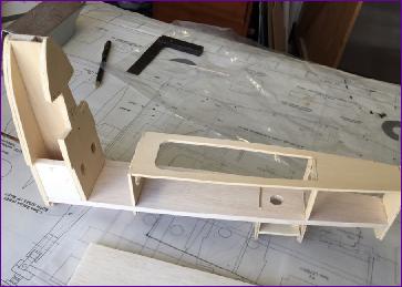
A base for the canopy was made up out of 1/8in balsa. Actually, the rear curved section was laminated in situ from two layers of 1/16in in order to hold the curvature.
I don't fancy the idea of fitting out that tall, narrow cockpit so plan to tint the canopy. I've been offered several ideas for how to go about this task but have to say I'm still not looking forward to it!
The fairings for the boom and mast were built up and then everything was given a first sanding.
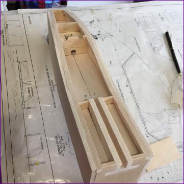
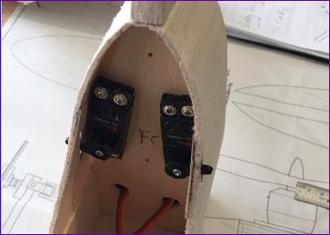
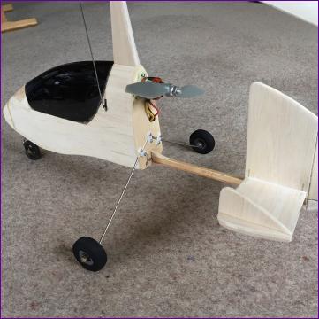
I took a tip from another builder and mounted the head servos upside down compared with the plan in order to bring the arm apertures clear of the canopy. In the picture you can just make out the pieces of 1/32in ply I added to reinforce the balsa round the edge of these apertures.
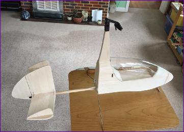
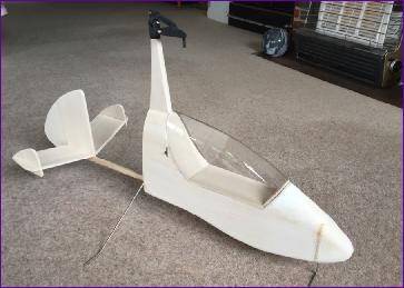
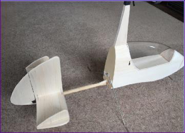
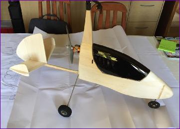
Then, with the end of the month in sight, it was time to assemble what I'd got, stand back and feel the sense of progress. Anything to put off tackling that canopy for a couple more days!
So, apart from that canopy, the main tasks still to go are the rotor blades and of course the covering. As yet I've given no thought to the colour scheme but it will probably be determined by what covering film I have in stock.
October 2019 Well, let's start with that canopy! A friend gave me a rattle can of Tamiya Smoke which looked ideal for tinting the canopy. The cunning plan was just to tint it enough to avoid the need for any interior detail. Said friend gave me detailed instructions on masking the outside, cleaning the inside surface with water and detergent, spraying in light mist coats from a suitable distance etc. - then he wished me luck and buzzed off to America for three weeks.
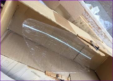
I was concerned that, with the outside masked off, it would be hard to see how the tint was building up so I hit on the idea of masking it with cling film. The next issue was how to hold the canopy open, to make it easier to spray the inside from a sensible angle. This challenge was met by clipping the canopy inside a cardboard box. So far so good.
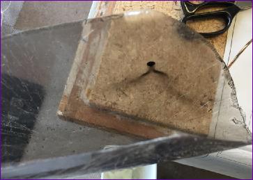
Out in the garage, I put the fan heater on to ensure the air was dry, gave the can a good shake, did a quick test spray on an offcut, then drew a deep breath and - made a right mess of it! I wonder now whether my cleaning was not thorough enough. Presumably there was some release agent used when the canopy was moulded and maybe I didn't get it all off. Whatever the cause, I was presented with a dribbly mess, with no alternative but to try and get it off and resort to plan B, which was to paint the inside solid black.
I had to use thinners to remove the paint, which seemed to have taken very well in places. This of course etched the plastic but that was of little consequence. What I didn't realise was that the fumes from the thinners must have reacted with the cling film in some way because when I tried to remove it, it had bonded with the canopy itself.
Anyway, so ended yet one more chapter in my litany of painting disasters. To be fair, the end result doesn't look bad if viewed from a few yards away. If it continues to annoy me or stir unpleasant memories it might get replaced some time in the future but it will have to do for now.
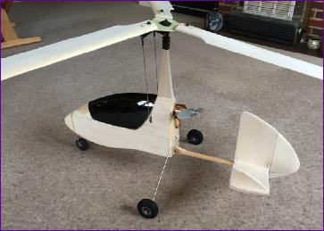
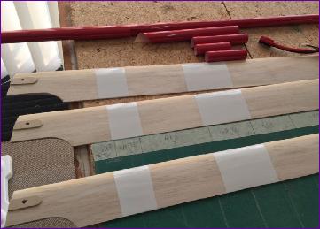
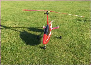
So, onwards to the blades. Having previously built the Panther, the blade building method was at least familiar to me and it all went very well. So smoothly in fact that I completely forgot to take any photographs. Balancing took only a few dabs of Balsaloc so, before getting the covering iron out, I put it all together for one last naked photo shoot.
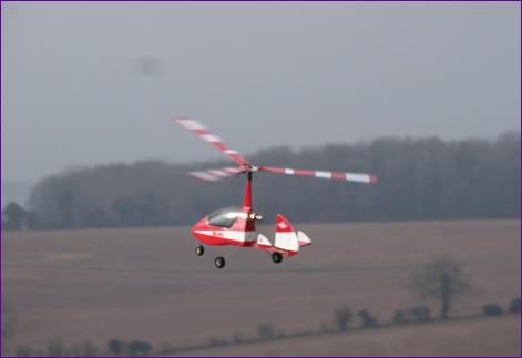
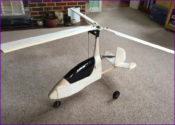
The overall red/white colour scheme was determined by existing stocks of film and based on another Revolver pictured on the RCM&E forum. However, when it came to the blades, I decided to replicate the design used on the Panther, the width of the white stripes following a Fibonacci sequence from root to tip, while the red sections follow the same sequence from tip to root.
In flight, this design shows as concentric circles when viewing the top of the rotor disc and solid red when viewed from underneath and I find it to be an invaluable orientation aid. Addition of the outermost white sections is left as late as possible so that the overlap (underlap?) with the red can be tweaked a little to assist with the final balancing.
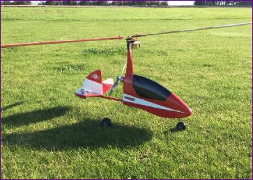
The recommended hang angle range is 14 - 18degrees. With the 3s x 2200mah battery firmly stowed in the nose, I measured it at 18degrees, which seemed okay as a starting point.
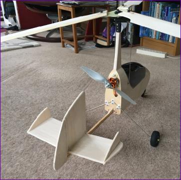
I'd failed to find a three bladed prop so, with a 9 x 6in two blader fitted, was not surprised to record a modest full throttle current draw of just 18amps. However, there seemed to be enough urge so that check box was ticked.
The plan shows 0.4mm ply shims ubder the blades but, based on experience with the Panther, I left these off. I did cut some suitable pieces of ply and take them with me to the field though, just in case the head refused to spin up without them.
Maiden flight day had a very light wind. A quick twirl of the head and the rotor rotated lazily. It was clear it wouldn't spin up to speed on the breeze alone but at least it did keep going so it looked like the shims would not be needed. After a long, steady take off run, I got just enough air under the wheels to establish that there was no immediate tendency to roll either way. This implied that the blades had got up to speed and that the roll trim was somewhere near - a promising start.
The model was retrieved for a second run. This time it again lifted off straight and level but I found I needed almost full back stick to hold the nose up so I settled it back down on the ground. Following advice received on the forum, I re-located the battery to bring the hang angle back from 18 degrees to 15 degrees in readiness for the next foray.
This time, at our local field, I was hoping for a bit more breeze to get the rotors up to speed before attempting take-off on our somewhat shorter runway. While waiting, I took the opportunity to photograph the Revolver with its big brother. Eventually with time moving on and no sign of the forecast breeze, after a brain tuning flight with the Panther, the Revolver was lined up and the blades given a twirl.
Maybe it is due to the trike undercarriage but it seemed that the model needed to go quite a bit faster than the Panther to get the blades going. However, as the end of the patch loomed, the Revolver was coaxed into the air and it was immediately clear that the pitch trim was much improved. In fact it was practically spot on. However., as the model came round in a gentle left hand circuit I found that I needed full right stick to get it to straighten up and there was no way it was going to turn right. So, a couple more left hand circuits were followed by an easy landing and a little adjustment to the pushrods.
By the time I was ready to go again the wind still hadn't picked up but had moved round to a less favourable direction, shortening the available take-of run even more. As a result, this time I definitely hauled it off the ground before it was really ready which made the first few seconds of the flight unpleasantly interesting. However things soon settled down and the roll trim was now much better and I was able to get the Revolver trimmed out for straight and level flight. At last I reckoned the time had come to try a couple of right hand circuits. For some reason there was a distinct tendency for the nose to drop in right hand turns so I reverted to the nice smooth left hand circuits, called landing and decided that was enough for today.
So, all in all, a very promising beginning. I'm sure that after a bit of experimenting with rudder trim and/or motor thrustline this will be a very sweet model to fly and I look forward to getting to know it better.
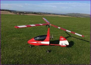
 This time, at our local field, I was hoping for a bit more breeze to get the rotors up to speed before attempting take-off on our somewhat shorter runway. While waiting, I took the opportunity to photograph the Revolver with its big brother. Eventually with time moving on and no sign of the forecast breeze, after a brain tuning flight with the Panther, the Revolver was lined up and the blades given a twirl.