LA Heli Rotorshape
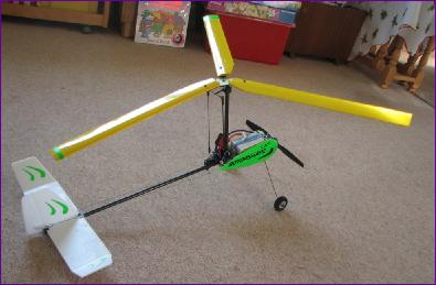
I find that it's always nice to have something a bit out of the ordinary to bring out when you're feeling in a bit of a flying rut. So, when I was looking around for a home for the gear taken out of the Miss Hyperion hydroplane, it was rather appropriate that this autogyro was the first model I came across that seemed suited to the motor and battery combination that was to hand.
There are no assembly instructions as such, just a couple of exploded diagrams and a parts list. However, there isn't a lot of room for doubt over what goes where and the main issues are more about what glue to use for which combinations of materials. The front bulkhead is in two parts which sandwich the wire undercarriage between them. Provision is also made to capture two nuts between them too, to facilitate motor mounting. I wasn't able to use these so left them out. Happily though the holes were more or less the right distance apart to reverse-mount the little Keda 20 28M. The motor comes with a screw-on adapter so there is no need to re-fit the shaft for reverse mounting. However, the tailboom fits into a hole in the bulkhead on the axis of the motor. No matter, the boom is hollow and, in spite of the significant downthrust incorporated, the protruding motor shaft can spin harmlessly inside the tailboom.
The next snag was when I discovered that my cheap Tower Pro servos were just too small to fit the plastic mounting pillars which are moulded into the rear bulkhead. This caused a fair bit of head scratching but eventually a combination of double sided tape and a ply clamping plate had them securely in place.
Then comes the tilt head assembly. This again is cleverly thought out, although I admit I wasn't able to make the tilt mechanism completely friction-free. If you enlarge this picture, you should just be able to see the tapped hole in the collar behind the mounting cradle into which the 3mm bolt screws. This means that the lift of the rotor will put a steady load on the servos in flight - I just hope that they are up to it!
With the mast installed, the business end of the model was practically done so attention changed to the tail end.
It was at about this stage that I realised that, having reversed the motor mounting, it would now run backwards so a quick bit of re-soldering was needed before the wiring could be tidied away.
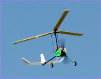
Flying Update Damage was fortunately limited to detached tail surfaces so before long we were ready to try again. Unfortunately the outcome was just the same except that this time the rotor mast broke free of its mounting at the rear of the pod so that marked the end of proceedings for the day. Such was the weather here in the UK in early 2010 that a full three months past before the Rotorshape came out of the car for another attempt at flight. In the meantime, I had scoured the web for other modellers' experiences with this model. Whilst many had flown successfully, I was by no means alone with my 'roll left into terrain'. The consensus view was that this problem arises from insufficient rotor speed at launch. To be honest, it was this discovery that was partly responsible for the long interval between flight tests - I took the model to the field on a few occasions but opted not to fly because there didn't seem to be enough speed to get the rotor really 'wooshing'. Eventually though, it had to be done. Same drill as before but this time I made really sure that I could hear an energetic wooshing noise from the rotors before giving the go ahead for launch. The Rotorshape flew away straight as an arrow, climbing steadily. To my surprise, it seemed to be pretty well in trim and, apart from a tendency to drop its nose in the turn, it handled reasonably predictably. A landing on the wheels rounded off a successful flight - well worth the wait. Twenty minutes later, we did it all again just to prove it wasn't a fluke. This time the Rotorshape did bank away to the left on launch, but controllably so, presumably indicating that the rotor speed was a bit marginal. Next time out, I wanted to get some flying pictures but was thwarted by finding myself alone at the field. This posed a dilemma: do I hand launch and risk having to grab for the sticks or do we go for a rise off ground? The grass was cut nice and short so I opted for the ROG. With full 'up' in to tilt the rotor back, I waited for a gust of wind to spin the rotors up, then eased the throttle forwards. The Rotorshape took off with no drama at all. After another landing on the wheels, I reckoned I was beginning to get the hang of this.
Apart from the shear pins, nothing else broke so all in all, this does seem to be a practicable flying machine - and it certainly is different! Click the link below for a heavily edited video clip.
|
||
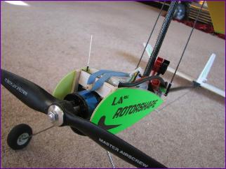
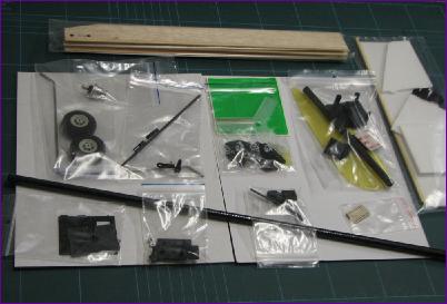 As you can see from this picture, this is by bo means an ARTF model. In fact it is an interesting mix of material: The tail surfaces are Depron, the rotor blades are balsa with spruce leading edges, the rotor mast and tailboom are carbon fibre tube, fuselage pod and floor sides are from thin fibre reinforced plastic of some sort and the front and rear bulkheads are of a flexible plastic with a waxy feel to it. (Guess who isn't too hot on plastic identification!)
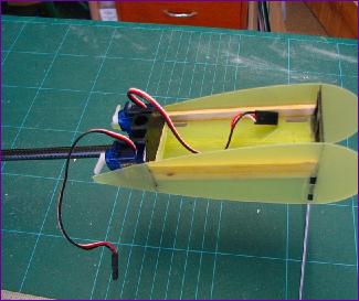 After a bit of filing, the various parts of the pod do interlock, so getting everything lined up is straightforward. However, there is really very little gluing are so, as you can see from the picture, I opted to reinforce the joints between the sides and baseplate of thepod with strips of balsa.
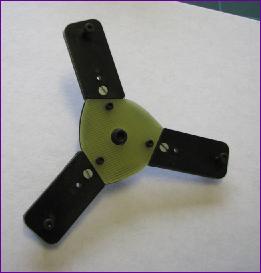 Next it was time to assemble the rotor head. This is actually quite a clever bit of design, incorporating two ballraces through which a 3mm bolt passes to serve as the rotor shaft.
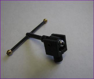
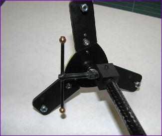 Here you can see the complete head assembly fitted to the rotor mast.
 There is no provision for a rudder in the kit as supplied but a couple of reviews on the web said that the model was improved by the addition of rudder control, so I cut one out of a piece of scrap Depron and set up a closed loop linkage to a third servo glued onto the underside of the tailboom.
 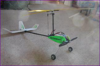 After fitting the decals and covering the rotor blades with SoLite, that was pretty much it.
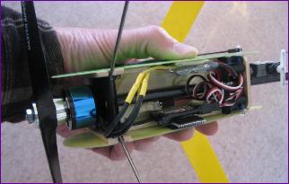 The motor is a little bit heavier than the one recommended and the battery is a bit on the large side too. However, it fits reasonably neatly into the pod and, with the extra servo and rudder on board, the weight came out at 317g - well within the recommended range of 300- 400g. By way of a bonus, the cg came out spot on too. Hopefully good omens for the maiden flight.
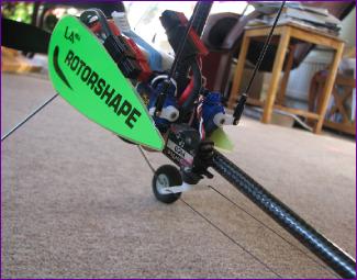
 Finally the opportunity arose to gather some evidence of flight. It took three flights before we got a take off and landing on video, mainly due to me taking off when the cameraman wasn't ready or messing up the landing. This did though give rise to another discovery: When the model turned over on landing it of course broke the 1/16in sq balsa shear pins. Rather than replace them, I poked out the remaining bits of balsa out, positioned the blades by hand and tried another take off. To be honest, I couldn't tell the difference so it seems that the shear pins aren't necessary and leaving them out does mean that the blades can be folded for transport and storage.