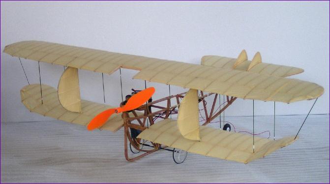
Stanger Biplane When I visited the local motorcycle museum one day, little did I know that this was to be the start of a fascinating research quest, which would result in my undertaking the most peculiar and challenging indoor flying project yet. A motorcycle bearing the name Stanger caught my eye because Stanger is the name of my maternal great grandmother. Also in the museum was an article about the motorcycle builder, a Mr. David Stanger who tuns out also to have been a significant model aviation pioneer and, with the model pictured above, set the first ever record for a petrol-powered model aircraft. Over the next few months, I assembled more information on Mr. Stanger, his models and his engines, which you can read in the Miscellaneous Zone of my website (click here for a direct link). As I marvelled at the man's achievements, I realised that, although some of his engines are preserved, none of his models had survived, indeed there seemed to be relatively few photographs of them either. As the Winter indoor flying season approached, I recalled that I had vaguely contemplated building a canard as my next indoor model, and had even got as far as downloading some three-views of a couple of Rutan designs, but had never actually taken the plunge and started building. David Stanger's canard biplane offered all the novelty value of a canard (and then some!) and although the prospect of all those curved wooden fuselage components and delicate wing structures filled me with forboding, eventually I could resist no longer. It was time to give Mike Roach a call..
The next decision was size. To avoid adding to the uncertainties, I opted to stick with the size and power regime that had worked so well with the SE5 and Walrus, which led to a scale factor of around 35 per cent to bring the original seven foot span model down to just under 30ins. First though, I sketched out the flying surfaces at half this size and built the chuckie shown below, in order to get an idea of what sort of angles the wing and canard should be rigged at and, of course, where to fit the centre of gravity!
The chuckie flew surprisingly well, so now it was time to work out how to build that fuselage framework. Still working at half size, I set about building a framework from 1/16in square balsa. I built it upside down, starting with the top horizontal frame, then erecting the 'A' frames on top, finally adding the curved keel piece. This approach threw up a number of problems, the main one being the way the keel piece splits in two at the front to support the foreplane and forefins. However, by viewing the framework from various angles, I was at least able to adjust the various strut positions to correspond as closely as possible with the original. This framework was then used to draw up double sized sketches so that building could begin for real.
Attention then turned to the wings. The main structural member used was a 2mm diameter carbon leading edge. Ribs and half ribs were cut from 1/16in balsa and a 1/16 x 3/16 balsa rear spar used to line up the ribs. I built the top wing in one piece, but the lower wing was built in two halves. There is no trailing edge as such, but cotton was later strung along the ends of the ribs to support the covering. Although a bit fiddly, this method of wing construction worked surprisingly well, the main problem being the vulnerability to handling damage. The all flying rudders were made by bending 1mm carbon rod and attaching it to a 2mm carbon rod upright, using Kevlar thread and cyano, to create the 'D' shape. Balsa ribs were then inserted. Using the rudders as a guide for length, 10 interplane struts were cut from 1mm diameter carbon rod and 1/16in balsa gussets fitted into the wings at the strut mounting positions. At this point I couldn't resist an attempt at fitting these bits together:
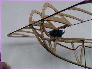
The foreplane was mounted on a pivot wire (actually 1mm carbon rod again) between the two up-curved points at the front of the fuselage. An HS51 servo mounted to the top of the fuslage frame was then connected to the rear of the foreplane by a short vertical pushrod.
After adding the cotton trailing edges to the wings, I gave them a good sanding, rounded off the various members of the fuselage framework and set to with a tin of Colron wood dye. After the dye had dried, the flying surfaces were covered in Litespan. Vertical surfaces were covered on both sides, but the wing and foreplane were covered on the top side only, as per the original. Finally, the vexed question of how to fit the wings; I could find no evidence in the photos of any attachment for the upper wing apart from the interplane struts. This meant that I would have to fit the lower wings to the fus and then use the inter-plane struts to mount the top wing, whilst somehow holding the whole lot straight. A short length of brass tube bound and cyanoed to the fuselage uprights served as a joiner for the leading edges of the lower wings, and the rear spars were then trimmed to butt up against the rear uprights and fixed in position to give an angle of attack similar to that on the chuckie version. There then followed much messing about producing cardboard jigs to hold the wings the right distance apart, so that the rear fins/rudders could pivot in short pieces of nylon tube glued into the wings (actually, the first use of the jigs was to get these pieces of tube glued in at something like the right angle).
First attempts at flight were unpromising. The model gathered speed along the ground well enough but then would execute a sharp pirouette, usually coming to rest with one shed tyre ignominiously rolling around the floor. After repeating this a few times, I began to realise what was happening. It seemed that the main wheels were lifting off, whilst the nosewheel was still grounded, resulting in the model trying to overtake its own nose. Having retrieved the model, the battery was moved back as far as possible and the foreplane rigging angle increased. Again the model seemed to gather more speed on the ground than I would have expected but, hauling back on the stick, it at last became airborne, and climbed away steadily. Turn response was somewhat delayed but adequate for the spacious Calshot velodrome, given a bit of planning ahead on the part of the pilot, and the model looked quite stately in the air. I was still having to hold in up elevator and I got the distinct impression that the foreplane was still working hard, suggesting that the cg probably ought to go back a bit further still. However, the mission of the evening had been accomplished so an early landing was called and I went home happy.
|
||
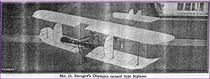
 As Mike and I pored over the photographs, it became clear that the biplane had been developed quite a bit from its early incarnation before it set the record in 1914. Indeed, the photograph in the 1910 edition of Flight, on closer inspection, turned out to be a tractor biplane! One can only speculate what persuaded Mr. Stanger to switch to the pusher canard configuration - news of the Wright brothers' success perhaps? As you can see from the two pictures here, it seems that the fins between the mainplanes were a later addition too. It didn't take me long to decide that I would base my model on the version with the fins, which are ideally placed to become all-moving rudders.
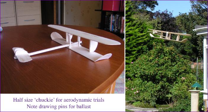
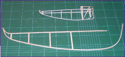 Bearing in mind the problems experienced with the half size version, this time I opted to part-build two side frames, then join them at the keel, whilst inserting the horizontal spacers between the upper longerons. The longerons were laminated from 0.8mm ply, the cross pieces from 3/16in square balsa strip (later to be sanded down to a round cross section). This approach was successful in that the desired splayed nose effect came about naturally and I was able to pull together the lower longerons all the way to the rear, leaving the rear curves in the upper longerons and the engine support rails above them to be fabricated separately from balsa and spliced into position.
 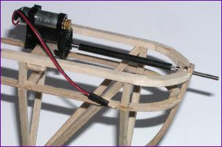 Whilst sorting out the rear end, I pondered how best to mount the motor. I slid a length of carbon fibre tube onto the driveshaft of the GWS unit and slid a spare driveshaft into the other end to create an instant extension shaft. This looked very promising and would enable the motor to be mounted where the original petrol engine had been fitted, so that I could hopefully conceal most of it with a dummy engine later. I fitted a spare GWS plain bearing into the rear of the fuslelage frame to steady the extension shaft. One more uncertainty resolved - or, at least, so I thought.
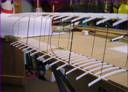
 The foreplane was constructed in a similar fashion to the wings, but here a 1mm diameter carbon rod was used for the trailing edge. Wing tips and the fore fins were fabricated from balsa and suddenly I found that I had accumulated a collection of parts and could no longer put off the tricky question of how they were all to be fitted together. I knew that, once the wings were fitted, the model would become quite hard to work on so, to put that off a little longer, I started at the front and worked backwards.
 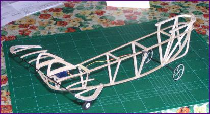 Next came the undercarriage. The nose leg on the original looks to be a complex affair but, for now, I contented myself with bending up a single leg out of 18swg piano wire. The main gear attachment is equally mysterious, so once again I opted to keep it simple and used a piece of 2mm carbon rod, with 18swg stub axles attached with heat shrink sleeving. More heat shrink was used at the centre of the axle to provide a snug fit into the hole above the keel of the fuselage. Having sorted these issues, the foreplane and undercarriage were removed again - it was time for some sanding and staining.
 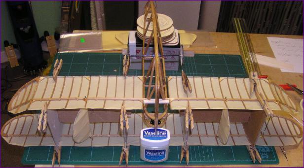 Over the next day and a half, I had several frustrating, fumbling attempts to
 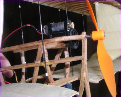 By now, the first Calshot flying session of the Winter season was drawing close but, because of the protracted struggle with the wings, it was clear that there was no way that I was going to be able to complete the rest of the assembly and get the model rigged in time for the event. Worse was to come: I pressed on and installed the rudder servo, driving the rudders with a closed loop of black cotton under the lower wing, then re-fitted the foreplane and undercarriage. This enabled me to do a trial balance to see where the battery would have to go. To my horror, the model was nose heavy even with the battery strapped to the rearmost fuselage upright! Sadly, the simplest way of dealing with this seemed to be to dispense with my extension shaft arrangement and relocate the motor as far back as possible. This done, I realised that the only thing now standing between the model and a maiden flight was the lack of rigging. I temporarily fitted the battery and carefully picked the model up by the wings. There was a little bit of flexing but basically, the wings held their shape. Rather than delay another month, I decided to take a chance and try for a maiden flight in the un-rigged state, in the hope of at least establishing the viability of the model, and finding out whether the cg position and rigging angles derived from the chuckie were somewhere near right.