As the 2002/2003 Winter season approached, I felt the need for something different for the coming indoor flying sessions. Having been pleasantly surprised by the performance of the SE5a, I tried to think through the secrets of its success and decided that a reasonably compact model using a heavily cambered section on a lightly loaded wing was a reasonable summary of the key ingredients for indoor scale - like flight. Without getting involved with expensive ultra miniature equipment, I couldn't see how I could improve much on the weight of the SE5, so the wing area ought to be much the same too. When I came across the Walrus, it seemed an ideal opportunity to build something dimensionally similar to the SE5a, but totally different in character.
The resolution was not very great, but nonetheless, I printed it out, worked out a scale factor to bring it up to about 30inches span and set to work.
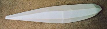
Boat building This aircraft doesn't really have a fuselage, more of a hull. Fuselage sides were cut out of Depron in the normal way, followed by a couple of bulkheads fore and aft of the wing seat. One more bulkhead was needed, positioned so that the sides adopted the right sort of curve when the nose was pulled in, then the tail ends were pulled together. Paper patterns were needed to work out the shape of the underside panels (chines?), and all of a sudden it was looking pretty boat-like.
Bird bits In many ways the wings were the easiest bit. They were cut out from Depron and a section formed into them by rubbing each panel in turn over the edge of the kitchen worktop. The panels were left for a week or so to settle just to make sure that the amount of camber was similar in all four panels. The bottom panels were butt jointed with the characteristic sweepback and just a little dihedral, as per the full size. The upper wing is swept back by the same amount but has no dihedral. The trailing edge is relieved to clear the propeller.
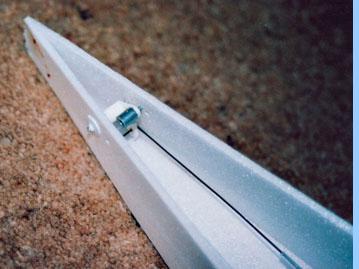
If the wing was easy, the tail surfaces were anything but! Admitedly, part of the difficulty was self-inflicted as a result of accepting the challenge from a fellow modeller to do an internal linkage to the elevator. After much thinking and tinkering, the fin was fabricated from two thicknesses of Depron, held apart in the centre by two strips of 1/16in balsa. The gap between these strips formed a channel for a thin wire pushrod, which would connect to a 120degree crank mounted in the fuselage (and yes, that is blood you can see on the tail end!). All that remained now was the problem of coupling the wire pushrod to the elevator. Some time ago, I read about a way of connecting pushrods to torque rods using heat shrink sleeving. I remember being somewhat sceptical of the idea at the time, but now it seemed the only way of making a hinged connection within the 1/16in gap between the fin sides. Even so, it took a lot of experimentation and head scratching to get the geometry right and work out an assembly order for it all, but eventually everything seemed to work reasonably smoothly. After this, it was something of a relief to rig up a conventional thin wire snake connection to the rudder!
Techy bits One of the first things I did after printing out the three view was work out what size prop could be accommodated without taking slices out of the fuselage. With my chosen scale factor, it seemed that, if I cheated just a little with the thrust line, I could squeeze in a 7in prop. After making a few enquiries, I was directed to the GWS web site to find that, in addition to the well known IPS motors and gearboxes type A, B, C etc., which are geared at 6:1 upwards, GWS have now introduced two more versions with lower gear ratios, designated S1 and S2. Looking at the helpful chart on the back, it seemed that the S2 unit should work with their 7x6 prop so - one more decision made.
The rest of the on board gear was as per my other indoor models, so now it was just a question of how to mount that motor in its pod between the wings.
Strut stuff I bought some 0.5mm carbon rod for the outboard interplane struts and some 2mm rod to support the motor between the wings. The pod structure is built around a balsa stick onto which the GWS motor unit slides, with two more short lengths of the same balsa stick glued across it. Carbon struts were then poked through these two cross pieces, adjusted to appropriate angles and cyanoed in place. The next problem was the nose cone on the pod. I did try to use half an an egg shell, but could find no way of trimming it without it shattering - ideas anyone? Attempt number two was papier maché over an old spinner. It soon became clear that this was going to use a lot of paper and glue, so most of the paper was removed and a coat of epoxy resin applied. The result is far from perfect, but I tell myself that the full size probably had a few dents in it too! Finally, Depron formers and planking were used to build up the shape of the rest of the pod, and then the supporting struts were threaded through holes in the wings. Once everything was lined up, with the outboard struts in place, a few spots of cyano finished the job.
Assembly As I offered up the wing assembly to the hull, I was struck by what an improbable looking machine the Walrus is! If you can blot the hull out of your mind, the relative positioning of the flying surfaces is remarkably conventional. However, with that aft mounted propeller sending its corksrew blast over the tail and that draggy hull hanging down below like the gondola on an airship, one can't help but wonder. One of the things I wondered about was rigging angles. The SE5a does fly a little tail-down sometimes, so I wanted to ensure that the wings of the Walrus were rigged at a slightly higher angle of incidence. Whilst checking the alignment of the tail surfaces with the wings, I temporarily attached the wings with elastic bands - and instantly decided that, at least for the proving flights, that was a pretty good way of attaching them! At that point I realised that, apart from a gaping hole where the cockpit should go, there was nothing much standing in the way of a test flight.
Test time Having built a simple cockpit cum hatch, fitted some wheels and adjusted the battery to balance the model at a randomly chosen point, I put it in the car on my next trip to the flying field. Well, with an unknown rudder/elevator design and virtually no dihedral you didn't think I was going to do the first flight indoors, did you!? General opinion was that the cg was within a few centimeters of where it should be and so, this unlikely little white ghost of a model was gently placed in the air with the motor running at about two-thirds throttle (I was concerned that, at full power, the high thrust line and that draggy hull would result in too much downward pitching moment). The first couple of seconds were pretty lively, but once I had worked out that full left rudder trim was needed and that one third throttle was more than enough, things settled down and the Walrus cruised around quite happily. The turn response was remarkably positive and I felt that it should be flyable within our usual indoor venue. Just to make sure, I decided to see just how tightly it would turn. With more and more bank and more and more power, the little plane was whirling round on the proverbial sixpence - when something went crack and suddenly there was a lot of dihedral! Returning rapidly to cruise speed saw the wings partly flatten out and a safe landing was made. Inspection revealed no real damage - it seems that the outboard struts, although still attached to the wings, were no longer locked at the desired angle, so the whole wing assemble could distort in parallelogram fashion. That's why the full size uses rigging wires, I guess!
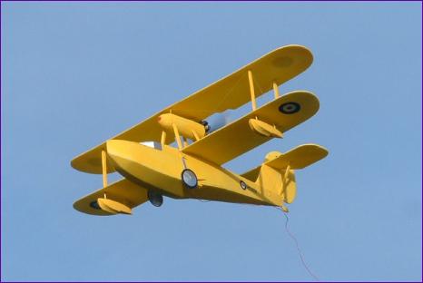
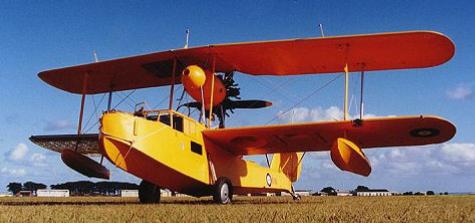
Finishing Readers of my reviews will know that I don't like the finishing stages of model building very much. However, it is much easier to commit to the effort involved once one knows that the model is worth it. So, after a successful test flight, it was time to return to the internet to find a suitable colour scheme. I really didn't want a camouflage scheme - apart stretching my very limited painting prowess, the concept of camouflaging remotely controlled models has always struck me as fundamentally flawed. Eventually I stumbled upon this recently restored example in the RAAF museum. Perfect - one colour all over, and bright yellow to boot!
The model was sprayed with Tamiya Acrylic paint, then the interplane struts were faced with Depron and kevlar rigging added. Dummy undercarriage struts were also made from Depron and wheeldiscs cut from paper. The main cockpit windows are from silver trim, edged with a marker pen.
The dummy engine is made from depron discs glued together and then the gaps between the cylinders were cut out. It was painted black and generally smudged with silver paint . I managed to find some old transfers for the fuselage roundels, but those on the wings had to be cut from trim. Mike Roach was good enough to cut me some tip floats from pink foam. Rub down lettering was used on the fuselage which surprisingly worked without problems onto the painted Depron. The pictures on the log book and key data pages show the finished model.
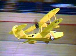
The only flying shot at the moment is this video frame grab (which you can click on to enlarge). In finished form, the model flies very well - you can judge the flying speed from the angle of dangle of the aerial wire. In cruising flight, the model turns well in spite of the lack of dihedral but I must admit that I have not yet tried flying the Walrus in the smaller halls. With most indoor models, the threat of an approaching wall can be countered by pulling a bit of up elevator and applying full power, whilst of course holding full rudder. This produces a sort of chandelle cum stall turn which is usually enough to get you out of trouble. With the Walrus though, this doesn't work because full power simply pushes the nose down so, instead of turning more sharply it merely accelerates towards the approaching wall. I am currently experimenting with coupling up elevator to the throttle to counter the effects of the high thrust line.
 If the wing was easy, the tail surfaces were anything but! Admitedly, part of the difficulty was self-inflicted as a result of accepting the challenge from a fellow modeller to do an internal linkage to the elevator. After much thinking and tinkering, the fin was fabricated from two thicknesses of Depron, held apart in the centre by two strips of 1/16in balsa. The gap between these strips formed a channel for a thin wire pushrod, which would connect to a 120degree crank mounted in the fuselage (and yes, that is blood you can see on the tail end!). All that remained now was the problem of coupling the wire pushrod to the elevator. Some time ago, I read about a way of connecting pushrods to torque rods using heat shrink sleeving. I remember being somewhat sceptical of the idea at the time, but now it seemed the only way of making a hinged connection within the 1/16in gap between the fin sides. Even so, it took a lot of experimentation and head scratching to get the geometry right and work out an assembly order for it all, but eventually everything seemed to work reasonably smoothly. After this, it was something of a relief to rig up a conventional thin wire snake connection to the rudder!
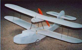
 The only flying shot at the moment is this video frame grab (which you can click on to enlarge). In finished form, the model flies very well - you can judge the flying speed from the angle of dangle of the aerial wire. In cruising flight, the model turns well in spite of the lack of dihedral but I must admit that I have not yet tried flying the Walrus in the smaller halls. With most indoor models, the threat of an approaching wall can be countered by pulling a bit of up elevator and applying full power, whilst of course holding full rudder. This produces a sort of chandelle cum stall turn which is usually enough to get you out of trouble. With the Walrus though, this doesn't work because full power simply pushes the nose down so, instead of turning more sharply it merely accelerates towards the approaching wall. I am currently experimenting with coupling up elevator to the throttle to counter the effects of the high thrust line.