DHC Chipmunk Project Diary by Trevor Hewson
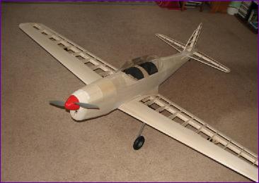
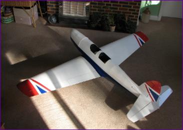
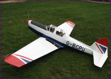
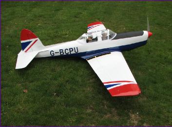
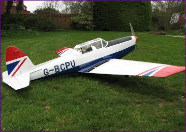
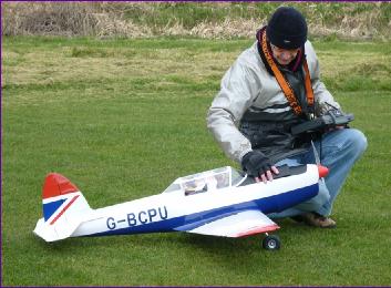
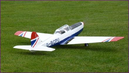
Having built two of Ivan Pettigrew's designs (the Sealand and Rapide) I made the pilgrimage to the Chilliwack fly-in in May 2010. We were made very welcome by Ivan and his clubmates and he insisted on us taking away a complimentary plan. I chose the Chipmunk. This choice was partly motivated by having seen three examples of this model fly equally well and partly because, compared to the T61 Falke which was then dominating my workshop, the Chipmunk, at 75in wingspan seemed a little less daunting. The following monthly diary entries detail the build progress, which was also recorded as a thread on RCGroups. |
||
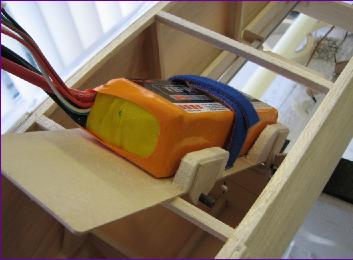
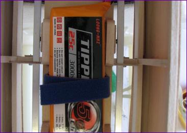
November 2010 (More on November) i) Oleos: This will be a first for me. After a helpful dialogue with Untract, I ordered a pair of their sport oleos - more details on the November page. ii) Flaps: I have enjoyed playing with the flaps on the Astro Hog although it really is too light to need them. The Chipmunk will hopefully be on the light side too but we shall see. iii) Hatch: The plan shows a long hatch from motor bay to wing trailing edge which certainly gives great access but is it really necessary? The only access needed when the wing is in position is for battery changing so a hatch in the anti glare panel will hopefully suffice. Everything else should be accessible through the wing aperture. iv) Power: Even though the three examples mentioned all fly perfectly well on 3 cells, it still looks to me like a 4 cell model (and I've got too many three cell models already!).
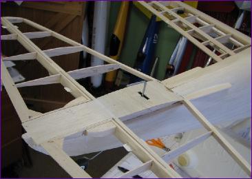
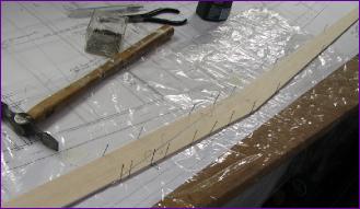
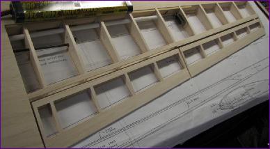
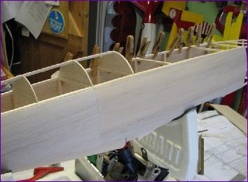
The rear section of the wing was built first, with paper tubes built in to accommodate the aileron servo leads.
|
||
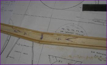 Anyway, as is becoming my standard practice, I tackled the wing first. The spar is from 1/8in balsa re-inforced with hardwood strips for the inboard section. The basswood strips I used are slightly oversize - my supplier didn't do 3/16 x 1/8. Because of the dihedral, they have to be spliced so, when it came to the doubler shown on the lower spar, I laminated this out of two pieces of 1/16 so that it could be bent round the dihedral angle, avoiding a join at the centre. The science behind using one lamination of spruce and one of basswood is complicated - it just happened to be what I had in the scrap box.
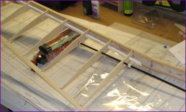 Because the wing is built in one piece, the flap control rod also has to be built in as the ribs are fitted.
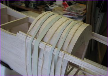
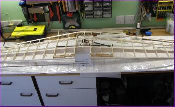 With the front rib sections, undercarriage bearers and false leading edges added, the wing framework is really taking shape.
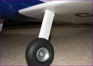
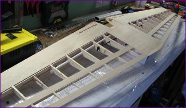 By the end of the month, the underside of the wing was sheeted in and I could test-fit those oleo legs.
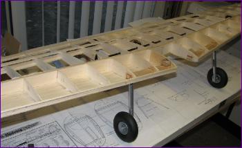
December 2010 (More on December) Then it was time top separate the ailerons and flaps from the wing:
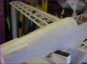
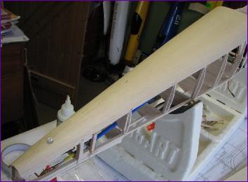
I decided to press on and fit the leading edges and wingtips before moving on to the fuselage.
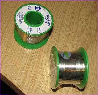
Despite double checking the order, it was only when I received the despatch notification that I spotted I had ordered yellow 8mm instead of green. When the package arrived, it was surprisingly heavy. The reason became clear when I found that the 5mm white LEDs which I (correctly) ordered had somehow morphed into reels of solder! When I found that the appropriate size was indeed 8mm and furthermore that the mounting clips I had ordered didn't seem to enhance the appearance, the net result was that, out of an order for ten LEDs and eight clips, only one LED was of any use. Just as well I wasn't ordering anything expensive!
The resulting framwork is quite flimsy - it will be stiffened up by the 1/16in skins to be applied later but I wanted to get as much of the internals sorted out first.
I am hoping to get the basics of the wing fixing and motor mounting arrangements sorted before embarking on sheeting the fuselage but it may be that some skins have to be applied to make the structure rigid enough before that can be done. Anyway, that's a challenge for the new year! |
||
 The next stage of fitting the missing end ribs, facing the front of the control surfaces and false trailing edge of the wings, fitting hinges and control horns, sorting out linkages and adjusting the gaps always seems to take a lot longer than I expect. Although having just listed what is involved, I suppose it's probably not altogether surprising!
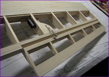 Whilst the ailerons are top hinged with exposed horns on the underside, the flaps are bottom hinged with internal linkages.
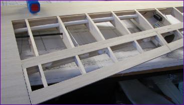
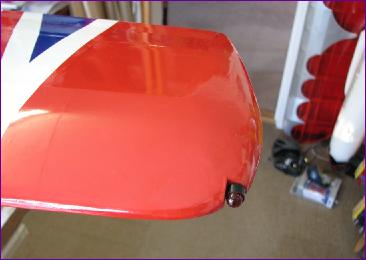
 Whilst I didn't want to bother with working nav lights, I felt that some non-working LEDs set into the wingtips would be a nice detail. I was unsure what size would be best so I ordered some red and green LEDs in 8mm and 10mm. Just to cater for any mishaps, I ordered two of each. While I was at it, I also ordered a couple of 5mm white LEDs for the light in the tail fairing. At least, that was the idea.
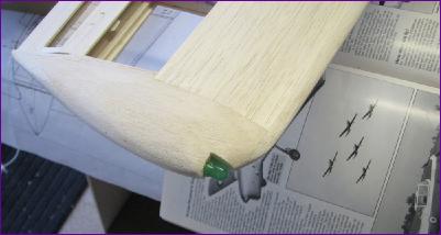 At this point the wing was put aside and a start made on the fuselage. The construction is reminiscent of the rubber powered models of the 1960s and starts with two side frames built on top of each other over the plan. These are then joined together with more 3/16in square balsa sticks.
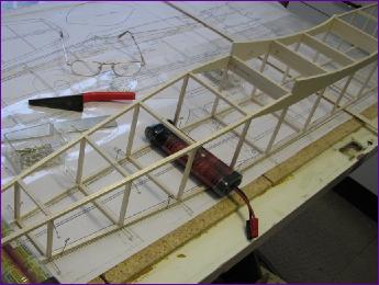
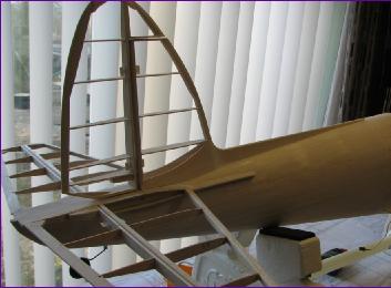
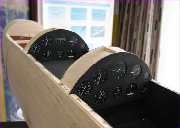
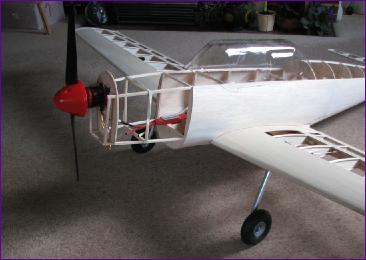
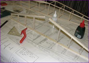 Once the tailplane and fin were built, the next priority was the rudder, tailwheel and elevator linkages. These are all hidden away inside the fuselage so space is a bit limited. After a fair bit of fiddling though, I was quite pleased with the final setup.
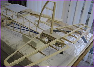 There are more detailed shots, as always, on the
 January 2011 (more on January)
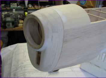
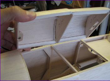
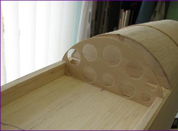
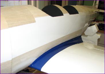
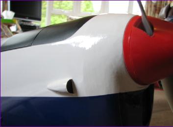
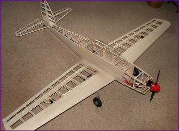
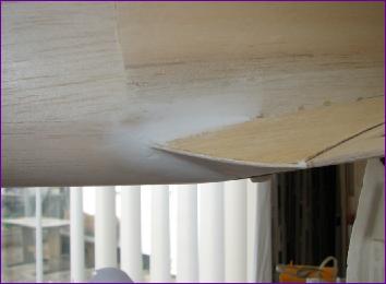
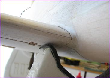
The remaining formers were added, including one immediately behind the wing plate, then the 3/16in square balsa stringers. All of a sudden the fuselage is beginning to look a lot less boxy. |
||
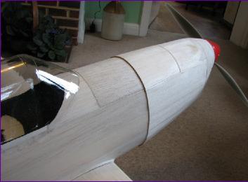
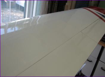
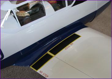
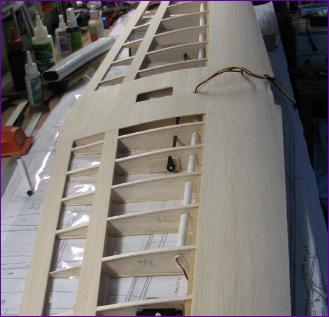
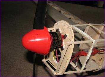
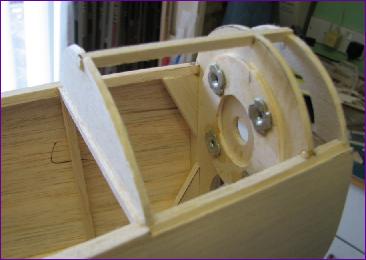
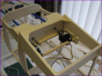 The rounded fuselage underside and the wing trailing edge are not exactly natural partners but, after a bit of head scratching, I decided to ignore the contouring of the fuselage for now on the basis that the wing fairing would cover this area eventually. A 3mm ply plate was used to take the T-nuts for the 6mm nylon wing bolts.
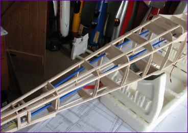 The servos are still accessible through the wing seat. The balsa former visible in the top left of this picture marks the approximate rear limit of the wing fairing so hopefully it will be possible to blend everything in without the corners of the wing plate sticking out!
|
||||||||||||||||||||||
|
||||||||||||||||||||||||||||||||||||||||||||||||||||||||||||