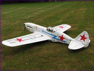
MiG 3
As I contemplated pensioning off my Limbo Dancer after over six years of good service, I began to think of putting the Ultra motor into a fighter of some sort. I have never done a true warbird with retracts and, with the advent of LiPo batteries, felt that it ought now to be possible to convert an ARTF i.c. model without too much of a weight penalty. After a few hours on the web trying to sort out the differences between the various Mustangs, Spitfires etc. on offer, I was getting a little jaded when all of a sudden I came across this model. With its white colour scheme and bold red stars it looks totally different from the average warbird. True, it is only semi scale but, whereas a poorly proportioned model of a well known fighter such as the P51 instantly looks wrong, most of us have no such ingrained blueprint of the MiG to generate such negative feelings. I did have a search for the model at the Sandown show of 2006 but without success. Then the Astro 15 in the Cub burnt out and the Ultra motor got pressed into service there, so the warbird project went on the back burner. Not for long though! A month or so later, I finally crashed the Logo 10 helicopter. A first estimate of the cost of the parts needed to fix it came to over £200, so I decided that I would rather spend my time and money applying the newly liberated motor and radio gear to something new and different. As luck would have it, the next weekend was the Woodsprings model show, and what is more, after inspecting a couple of P51 offerings, I turned to the next trade stand and there was the MiG 3. This kit is by Air Loisirs, but is made in Vietnam and also bears a 'VQ' logo, so it may be marketed under other brand names too. There was a review of the Air Loisirs Macchi C205 Veltro in the August 2006 edition of Aviation Modeller International (which, due to the time-warping date conventions of magazine publishing in the UK, I was able to read before buying the MiG two months earlier, if you see what I mean). It is clear that the two models are very similar, and certainly all the various criticisms levelled at the C205 such as missing spinner, poor quality wheels, mismatching paint, fiddly retract installation and poor instructions are equally applicable to the MiG. So too though are the good points: Construction quality is good and lightweight, the main components fit well and line up with each other. Apart from the tailwheel, all hardware parts were useable, although I couldn't bring myself to use nylon clevises on the elevator and aileron linkages. One of the distinguishing features of this model is the covering. This is pre-printed with panel markings etc, but the material is more reminiscent of that '60s shelf covering favorite, Fablon, rather than the heatshrink materials we are used to nowadays. That said, it was wrinkle-free and well applied and I suspect will prove to be very stable when parked out in the sun. We shall see.
For someone with the right skills and equipment, I have no doubt that bending the legs accurately is perfectly possible. However, I felt that my chances of getting it right were not very good so I sat down with a cup of tea instead. Eventually a memory stirred. Six years ago, I built the DC3 and fitted the optional retracts. The kit though included all the parts for a fixed u/c - including some axles. A bit of rummaging in my bits box soon located them but the holes in the axle hubs were imperial whilst the Air Loisirs u/c legs were metric. However the wire almost went in and I felt that easing the hole in the axle hubs was a much less hazardous process than bending the legs. Of course, it did mean that two more flats had to be ground on the legs for the setscrews in the hubs but, if these were not initially spot on in position or angle, they could at least be adjusted with a touch more grinding. On offering up the retract units to the mountings in the wings, I found, just as in the AMI review of the Veltro, that the bearers had to be relieved in order to accommodate the retracts. Once in there though, it was reasonably easy to adjust the retracts to close neatly into the wells. Bending the wire operating pushrods to shape was a bit of a challenge but, once I decided to ignore the drawings in the instructions and instead bend up a dummy pushrod out of softer wire by trial and error, I got on a lot better. With a standard retract servo installed and a few more slivers of balsa and plastic removed here and there, the retracts eventually worked well, locking positively in both up and down positions. Joining the wings posed no great problem. The dihedral brace did need easing a bit but then the wing roots lined up accurately. Just as well really since, although the instructions tell you to check the dihedral, no actual measurement is quoted. Next comes the aileron servo and linkage. This model is perhaps a bit unusual by today's standards, using a traditional single servo and torque rods rather than two separate servos. The ailerons are full span and are already hinged, with the torque rods fully fitted so, starting from here, there is little point in contemplating changing anything. I did though fit a mini servo rather than a full-size. After all, I did have four of them left over from the helicopter.
Elevators and rudder are supplied hinged to their fixed counterparts. However, when I cut the fuselage covering away to reveal the tailplane slot, it was closed at the rear end. The instructions show the tailplane being inserted with one elevator removed and a quick tug at the elevators confirmed that the hinges were not actually glued in. This sent me off for a quick check of the ailerons and rudder just to confirm that these really were firmly stuck. They were. It will come as no surprise to learn that the tailplane slot had to be eased somewhat but, yet again, once in there, the tail surfaces lined up perfectly. Installation of the rudder and elevator servos and associated linkages (substantial piano wire pushrods running in pre-installed guide tubes) was straightforward, so the rudder and elevator hinges were glued into position and the tailwheel unit fitted. As mentioned earlier, the tailwheel was a weak distorted apology for a wheel and was substituted for one I had in stock. All that was left now was the cowl and canopy - plus of course a redundant engine mount and fuel tank. I hate canopies, so it was time to tackle the motor mounting so that the model could be balanced in order to work out where the battery would have to go.
Individually, I was quite pleased with my motor mount, battery box and switch mounting fabrications. However, when I came to assemble things, I found it all a little awkward. Basically the problem is that the ESC and switch have to be fed into place through a hole in the firewall, as the motor and gearbox are brought into postion. The battery box cannot be installed until the internal wiring has been positioned - then the retaining screws are inaccessible because of the motor. This situation was made even more awkward once I fitted some baffles and deflector plates to the motor mount to direct cooling air up to the motor, because I then couldn't get a screwdriver onto the bolts securing the motor mount to the firewall. However, once I swapped to socket headed screws, it all finally went together.
I won't bore you with the convoluted path of experiments which I followed over the next three weeks but essentially there were three problems: i) The Kontronik speed controller has difficulty starting the motor when used with a gearbox. ii) Having replaced this with a Hyperion speed controller, I encountered serious radio range problems. iii) The closely spaced ball races on the MEC gearbox struggle to cope with the cantilever load of the three inch alloy spinner. As you can imagine, one consequence of working my way through all of this is that the awkward assembly sequence of motor, controller and battery box grew into a major source of irritation. I did though manage a couple of flights with this power configuration which at least confirmed that the model was worth persevering with. Flight characteristics were very good - just the sort of smooth, groovy handling that one would want with a fighter. The retracts held up well, working off our grass field. On taxying back though, I found that one one of the legs was rotating in the retract unit, so I made a mental note that it was probably time to replace my 15 year old tube of threadlock!
The good news is that, having done the switch, both models are now flying well - and both are interference-free. The only downside as far as the MiG is concerned is that the Ultra motor is heavier than the Kontronik / MEC setup. As a result, the cg is further forward and this, combined with the overall weight increase, has led to a tendency to nose over on landing. I am still experimenting with adjusting the cg and it may be possible now to revert to the original plan of using a BEC and so shed the weight of the Rx battery. However, since the latter is behind the cg, this may result in some lead being needed at the tail. If the nose over tendency continues to be an issue, I may consider cutting out the plastic wheel wells and re-modelling them to accommodate slightly larger wheels.
|
||
 Construction starts with the retracts. Well, the instructions would have you join the wings first, but that would just make fitting the retracts that much harder. Not that it was totally straightfoward anyway. The legs have a flat ground on them near the top so that they are less likely to rotate in the retract assembly. However, the legs are supplied straight and need to be bent to form axles. With the position and orientation of the flats already defined, this means that the bend has to be made at exactly the right point and in exactly the right direction. Unlike Paul Merton, I didn't do metalwork at school and the very thought of this challenge brought me out in a cold sweat. However, I clamped the wire-bending jig in the vise and, after much measuring, checking and re-checking, placed the wire leg in it and gave a tentative heave - and promptly pulled the whole thing out of the vise!
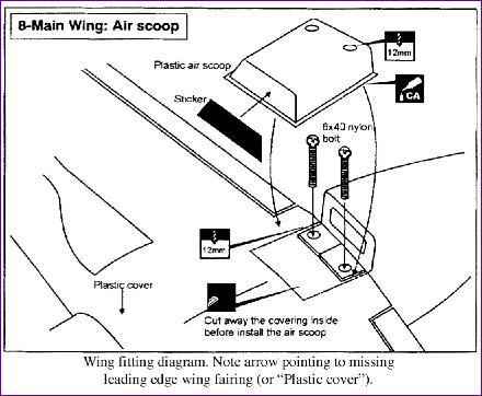 Fitting the wing to the fuselage again threw up the now familiar mix of good and downright peculiar that seems to characterise this kit. The slot in the leading edge bulkhead needed to be relieved quite a bit but, once this was done, the wing sat on the plastic wing seats well enough. The wing bolts went through the pre-drilled holes in the trailing edge and lined up perfectly with the captive nuts, and a quick check showed the wing to be nice and square to the fus. None of the above is really covered in the instructions. Instead there is just one illustration of how to fit the plastic air scoop (which incidentally fouled the wing bolt mounting plate because the latter had not been installed centrally). This illustration also bears the words 'Plastic cover' and an arrow pointing to where a leading edge wing fairing should go. However, no such fairing actually appears on the drawing, nor is it in the parts list, so it was out with the scrap box to fabricate one from balsa. Most peculiar.
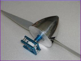 My calculations indicated that, on a 5 cell LiPo pack, the Kontronik Fun 600-15 out of the Logo 10 helicopter would need to be geared at about 3:1 to enable me to use a sensible sized propeller. I ordered an MEC superbox from John Swain at Fanfare, with a 50 tooth mainwheel and a 16 tooth pinion to give a ratio of 3.125:1. The Kontronik motor has a 5mm shaft, so I was careful to specify a 5mm bore for the pinion. When the gearbox arrived, I was struck by how little 'meat' there was left on the pinion with such a big hole through the middle. What is more, it was a brass pinion rather than steel, so I paid very careful attention to the dire warnings in the instructions about not over-tightening the grub screw. Instead, I used plenty of threadlock on the motor shaft as well as on the grub screw and gave it plenty of time to harden off.
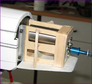 With the gearbox assembled to the motor, I set about building the mounting box you see in the picture, and then it was time to do a trial balance. This showed that the battery would need to go behind the firewall so, since I didn't fancy messing up the covering by cutting out the top hatch, this meant that the battery would be fitted through the wing aperture. After a quick rummage around the workshop, I found an Aveox motor box in which 5 3700mah LiPo cells were a snug fit so, with a little modification, a battery box was fashioned which slides through the apertures in the formers and is secured by two screws through the firewall.
 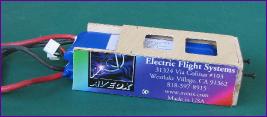 The battery is retained in the box by a piece of foam (ex- GWS receiver packaging), which in turn is locked in place by the wing. For safety, I decided to include a cut out switch behind the lower cowling so that arming the motor could be postponed until the wing was fitted and the model upright on its wheels.
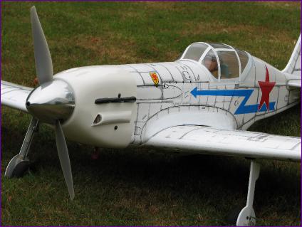
 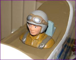 Whilst I was busy installing the power train, my clubmate, Andrew Tubb kindly painted the pilot, so he was duly installed in the cockpit and it was time to bring the MiG to life. It was here that my problems began!
 This first outing had confirmed that the radio range was still marginal and it was whilst trying to sort this problem that the limitations of the gearbox bearings started to cause concern. John Swain of Fanfare was very helpful, replacing a suspect bearing and offering lots of useful advice, but eventually I decided that it might be best to revert to plan A and put the direct drive Ultra 1300 into the MiG - which would mean that the Kontronik motor and MEC gearbox would become the third power plant installed in the Cub in as many months, but at least there it wouldn't have to cope with the heavy spinner. I have now done five motor installations for these two ARTFs - so I have written a separate