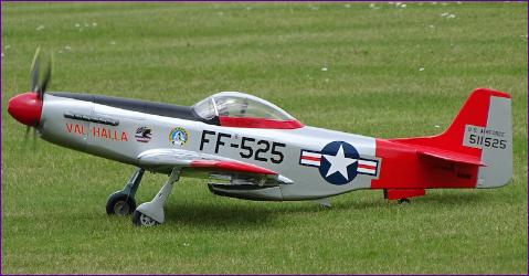
I’ve always found the Mustang a very attractive aircraft but somehow, until now, I’ve never got around to building (or even buying) one. During 2020 an online discussion was taking place, led by Richard Wills of Warbirds Replicas, on what might be a popular subject for him to produce as his next kit. After the usual round of suggestions of unusual types which, although undoubtedly interesting, were unlikely to have a wide enough following to make the venture viable, the Mustang eventually bubbled to the top of the list. By then though, I’d already decided that my 2020/21 Winter build wasn’t going to be a scale model and I was homing in on the Aeromaster as my project of choice.
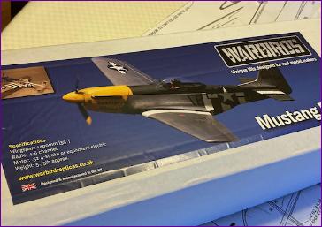
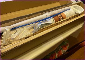
In the event, the kit arrived in November 2020 and, although the bench was full of Aeromaster, I allowed myself a quick look inside. The kit is very complete but there are always a few things to buy so over the next few months, the motor, servos, propeller etc. were purchased but the lid was kept firmly back on the box.
In the event, both of my earlier concerns proved well-founded - the Aeromaster build was indeed complete by the end of December and sadly we went straight into another Covid lockdown at the start of January - which we are still in as I write this first diary entry in early March.
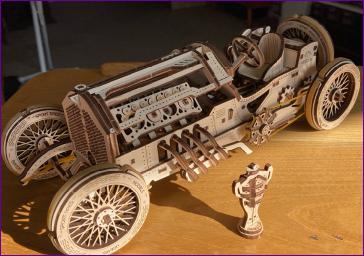
I kept myself busy with a few other projects during January, including tackling my more interesting Christmas presents such as this Grand Prix car by Ugears. However, with no indication when we might be allowed out flying again, the time had come to roll out the plans for the P51.
February 2021
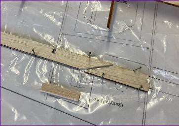
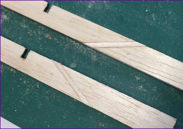
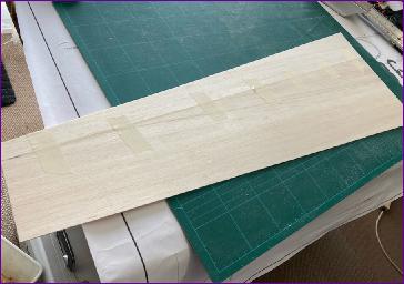
My kit is from the first production batch so there were always going to be a few glitches. Fortunately a couple of other modellers are ahead of me in this build and have helpfully flagged up some of these along the way. So before starting construction I extended the aileron spars which are about 3mm too short due to a late design change around the flap/aileron join.
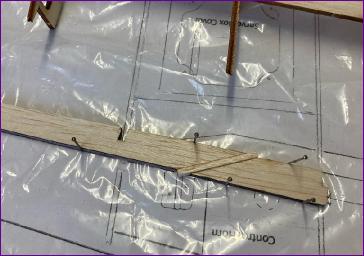
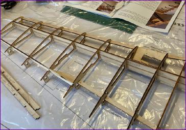
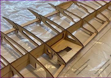
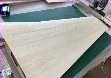
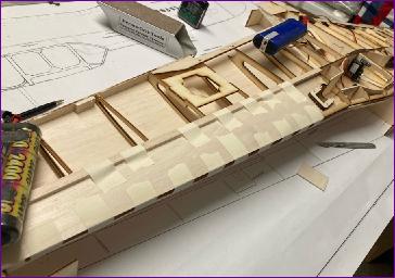
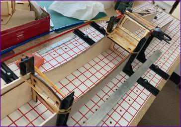
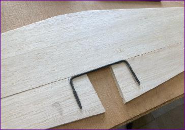
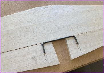
The basic wing structure consists entirely of laser cut parts, most of them ply, which slot together, making the assembly pretty much self-jigging. These two pics show a dry run. The idea is that, having got to this stage, thin cyano is wicked into the joints. I’m not keen on this approach, partly because I am sensitised to cyano, so instead dismantled the structure then put it together again step by step with PVA glue.
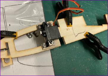
The root ribs (R1) are not glued in place at this stage, but I felt the need to do a dry fit of these, together with the dihedral braces, just to make sure that I understood how it all slotted together.
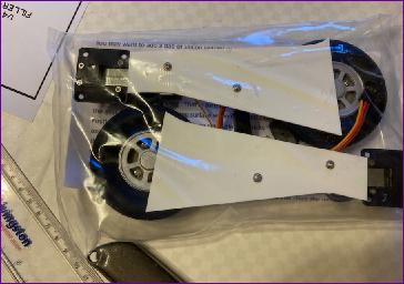
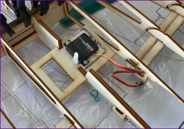
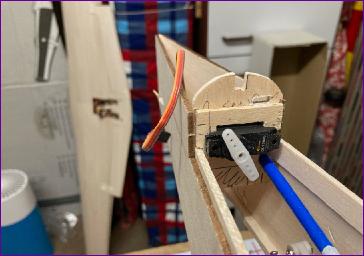
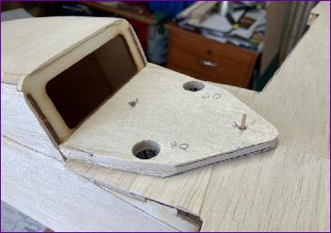
I also took the opportunity to check the fit of the flap servo mounting plate and sort out how I was going to attach the servo. In the end, I opted for a flat wing servo for this role.
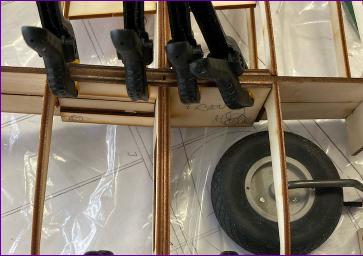
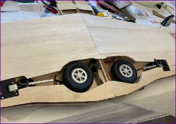
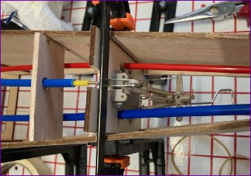
If you’ve read any of my previous kit-build accounts, you will know that I usually introduce some variation to complicate proceedings and in this case it was deciding to fit the inner undercarriage doors. These doors hinge more or less on the centreline of the airframe so there’s no room to fit a servo in between as I did on the P47. So the doors will need to be driven by vertical pushrods, with a servo mounted above the wing - unless there’s room to squeeze the servo into the retract bay itself. . . .
. . .As you can see, the servo fits in quite neatly onto R1. What I couldn’t be sure about though was whether the hinges, horns and pushrods could be arranged to give enough synchronised movement on both doors. After a lot of fiddling about, I convinced myself that it might work but, until the wings were be joined, it wasn’t possible to fit the hinges to test the idea fully.
The instructions recommend fully sheeting the separate wing panels top and bottom before joining them together. I wasn’t comfortable with this approach since I like to be able to clamp the dihedral braces firmly to the spar when joining the wings. However it did seem a good idea to get the top sheeting in place before bringing the panels together
The wheel wells were lined with 1/16in balsa then, after yet another dry run, the wing panels were joined for real. The resulting joint turned out somewhat neater than usual - shame it won't be seen! However, the joint is also strong, which is the main thing.
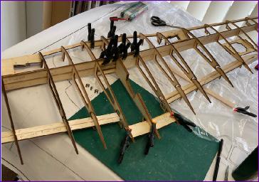
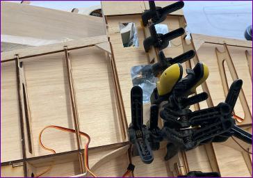
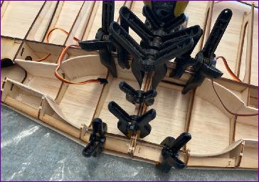
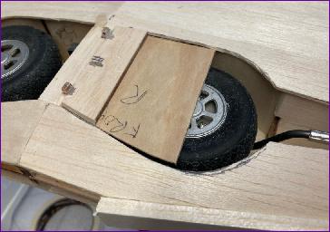
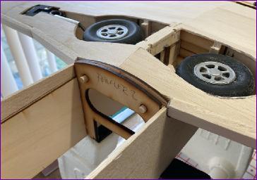
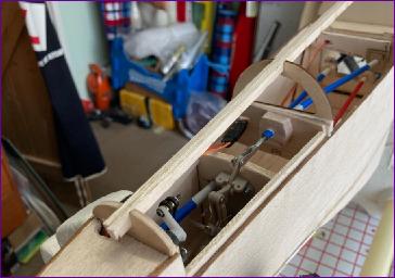
The flap servo linkages were next, then came what seemed like an endless (and at times hopeless!) spell of fiddling with the inner door hinges and linkages. These pics, taken after some serious grinding of ribs, doors and servo mounting bracket, show what a tight squeeze it is.
All this was done with some rudimentary mock ups of the doors themselves. which of course couldn’t be properly refined until the underside sheeting was in place.
To avoid any twist developing in the wings, each panel was placed in turn, inverted, in the supporting jigs while the underside sheeting was applied
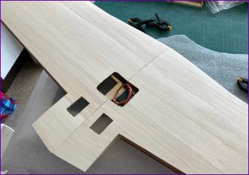
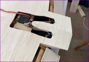
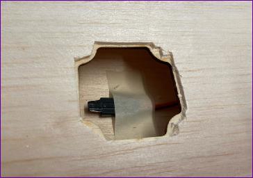
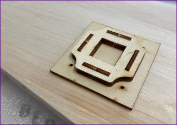
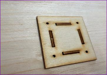
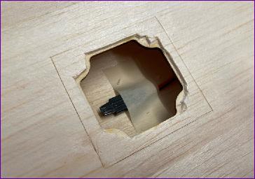
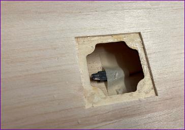
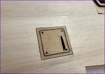
The aileron servo bays were then opened up. The photo sequence shows how, once the aperture in the mounting plate has been cleared, the supplied jig is inserted. Cutting around the outside of this jig results in a perfect fit of the 1.5mm ply hatch and frame, which then sits flush with the balsa sheeting. Very clever
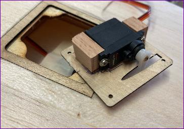
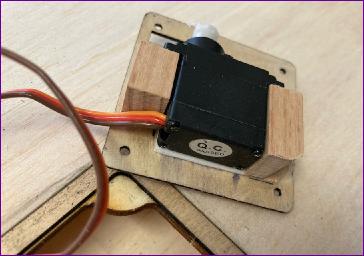
The servos are mounted on the underside of the hatch. I’m always a bit worried about the small glueing area for the hardwood mounting blocks so you will see that there is a sticky fixing pad under the servo as a bit of insurance.
Finally, the area around the retracts was sheeted, then the leading edges could be added.
I did make a start on trying to dress those inner doors. The idea was that, by laminating balsa on top of the 1/32in ply sheet, they could be sanded to the contour of the wing. Unfortunately, no doubt because I used PVA for the laminating, the doors took on quite a warp in spite of being clamped flat while the glue dried. I think I'll re-make the doors with the grain of the ply running spanwise and try to get the warp to work to my advantage, in the hope of reducing the thickness of the door, so giving a bit more clearance from the retracted wheel.
However, I've had my fill of gear doors for now and fancy a change of scenery so although there is probably another week or so's work left in the wings, as we enter March, I think I’ll tidy the bench and make a start on the fuselage - where another self-inflicted complication awaits.. . !
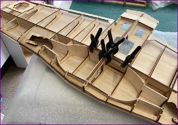
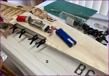
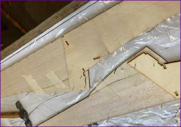
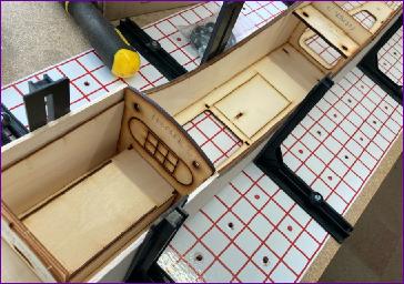
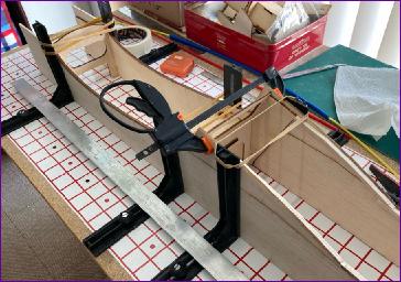
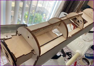
March 2021 The instructions for building the fuselage show the assembly of an extensive inner ply structure, followed by gluing the 3mm balsa sides in place. This ply structure is built around a horizontal ply crutch which ensures good alignment. However, because I had a few weight-adding modifications planned, I decided to leave this and a few other ply parts out, so instead started in the traditional way by gluing the ply doublers to the fuselage sides. Remembering the warping that affected the gear doors, I made sure to use plenty of weight and gave the glue plenty of drying time. With the doublers in place, the lower fuselage sides extensions were added before getting out the SLEC jig and doing a dry assembly, with the fuselage inverted. You can see the horizontal ply crutch in these pictures, which was used to double check the alignment. The last pic shows a minor alignment issue between the front former and the fuselage doubler.
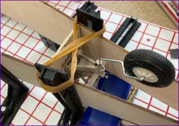
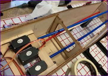
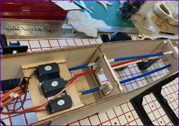
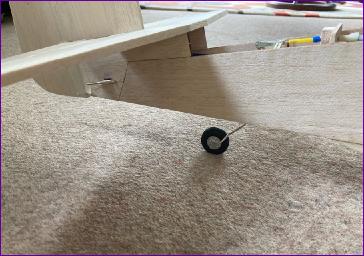
Still with everything dry-fitted, it was time to tackle the self-inflicted complication mentioned last month - a retractable, steerable tailwheel. A new former had to be made for this of course. Making the former and mounting the tailwheel unit to it was straightforward but the rudder and elevator snakes would need to be routed through this former, as of course would the closed loop wires to steer the tailwheel. The retract is servo driven so some thought had to be given to that arrangement too.
Eventually though, the thinking had to give way to action so the key formers were glued in place fore and aft of the wing seat, together with the wing bolt plate which, in the absence of the horizontal crutch, helps with the rigidity of the structure.
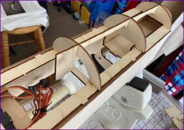
A servo tray was then installed, followed by a few days of messing about with snake routing etc. Once this was finalised, the tailwheel bulkhead was finally glued into place and the snakes installed.
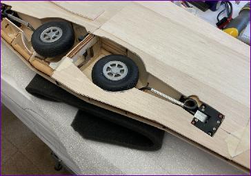
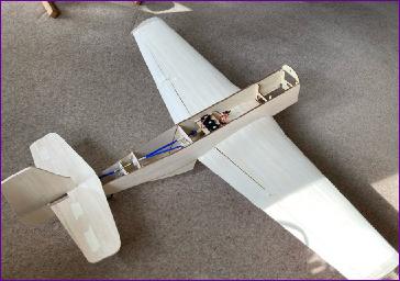
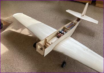
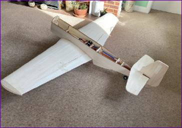
The next job was sorting out the wing fixing. All standard stuff but a job where care is needed to ensure everything lines up and fits well. With the tail surfaces pinned in place, the model could now stand on its own wheels for the first time - always a landmark in any build, and a source of motivation to continue.
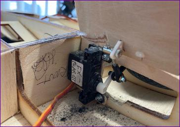
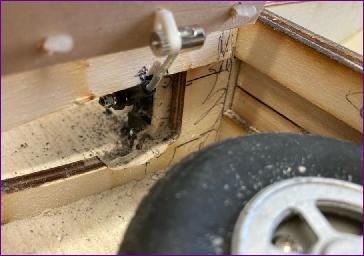
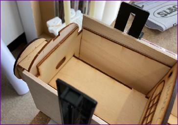
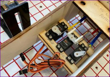
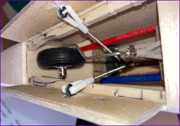
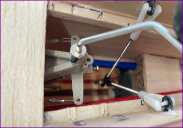
Then it was back to that tailwheel to sort out the doors. I wasted a bit of time trying to devise a mechanism for the retracting wheel to pull the doors shut but the design of the retract mechanism results in a very poor mechanical advantage towards the fully retracted position and it was clear that any additional load would cause problems. So I took the ‘easy’ way out and installed a dedicated servo. Even so, a fair bit of fiddling and adjustment was needed to get the doors working properly - and I was clearly so absorbed with the job that I forgot to take any pictures, so these retrospective pics peering into the depths of the fuselage, are the best I can offer.
Once the tailwheel retraction, steering and doors were all working, the underside of the fuselage was sheeted in and attention turned to the upper sections. Having initially decided to leave out the ply horizontal crutch entirely, looking at how the hatch and front deck formers fitted, it seemed easier to fit the front portion of the crutch after all. The rear part though was sawn off and omitted.
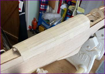
Looking at the curve on the rearmost former of the rear turtle deck, I didn’t fancy trying to roll a sheet of 1/16in balsa round it so instead planked the rear deck out of 3/32in balsa. Planking is not to everyone’s taste but I’ve realised over the years that, perhaps because it’s an incremental process, I find it far less stressful than wrestling with larger sheets. With little or no compound curve involved, this is a particularly straightforward planking proposition and, when sanded smooth, won’t represent any measurable weight gain and is a fair bit stronger than a rolled sheet of 1/16in.
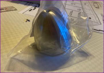
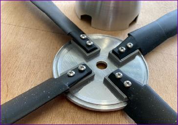
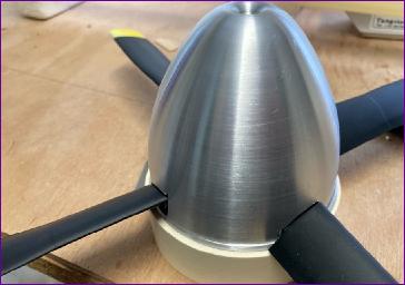
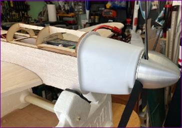
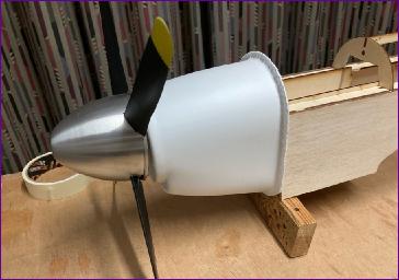
By now I was getting quite worried about what the addition of all the tailwheel complexity at the rear end was doing to the cg position, so felt the need to get an early check on the situation. This meant getting the front end up to the stage where the motor could be temporarily mounted. It also meant tackling one of the jobs I’d been dreading - cutting the slots for the four bladed prop out of that beautiful aluminium spinner! This was indeed a nerve-wracking job but in the end it went remarkably well. I found that, after sawing slots at the leading and training edge positions of the blades, the diagonal line between them could be scored, then the piece could be gently flexed and the aluminium would ‘fatigue crack’ along the scored line. A bit like glass cutting in ultra slow motion!
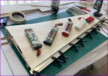
Finally I reached the point where the model could be roughly balanced. To my surprise, with a 4s x 3300mah battery on board, it is nose heavy. This is good news since, in my experience, the cg only ever migrates rearwards from this point onwards. I do though hope to be able to fly this model on 4s x 5000mah batteries so may need to extend the battery box rearwards. This trial assembly also highlighted the need to open up the rear hatch former and the corresponding front deck former to accommodate the larger battery packs, so it was a worthwhile, if diversionary, exercise.
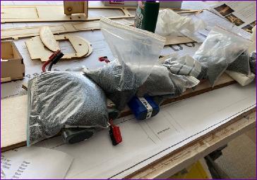
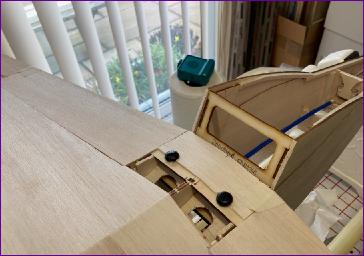
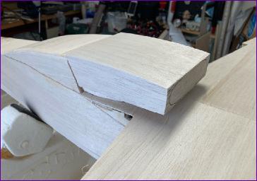
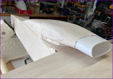
The radiator is a characteristic part of the P51 so, eyeing up the huge block of balsa provided to make it, I decided to take advantage of a spell of decent weather to tackle it, so that the bulk of the sanding could be done outside. First though the radiator mounting plate had to be attached to the wing. The instructions say to carve a shallow ‘v’ shape into this plate so that it accommodates the dihedral of the lower surface of the wing. I duly did this but realised afterwards that it would have been much easier to cut the block in two, glue the two halves to the wing separately, then plane and sand the surface flat to receive the radiator. I also found that the plate needed a bit of adjustment after installation to bring it into line with the fuselage sides.
With the plate fitted, the radiator was temporarily located on a couple of cocktail sticks and retained with a few patches of double sided tape while it was blended in to the rear fuselage sides. It was then removed again to complete the rounding off and fit the plastic nose section. Looking at this picture, it may be that that plastic section needs to be shortened a bit?
As the easing of the coronavirus lockdown at last drew nigh, bringing the prospect of at last getting out to do some flying, the last job of the month was to make a start on the tail surfaces. Hinge slots were cut in the elevator and tailplane as were the holes and grooves cut for the wire elevator joiner. I did shorten the joiner wire a bit since I feared that it might otherwise emerge when the elevators are sanded to section.
So, there goes another month! In some ways there's not that much left to do but some of the jobs are quite time consuming so I'm guessing that progress will look rather less impressive next month - particularly if we get some decent flying weather! Click here for Part 2.