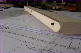
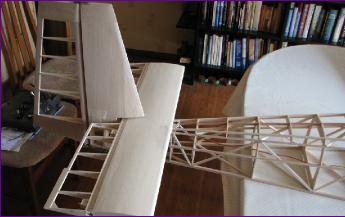
Because I used balsa instead of ply to skin the tailplane, the hinge shrouds had to be added seperately. I set the hinges in carbon fibre tubes for added support.
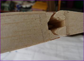
The leading edge of the elevator was built up with two pieces of balsa strip rather than a single solid nose.
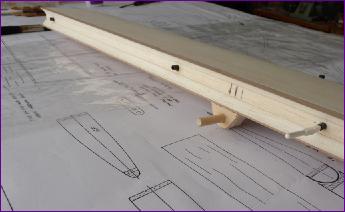
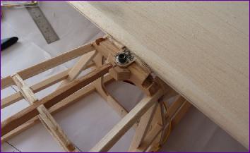
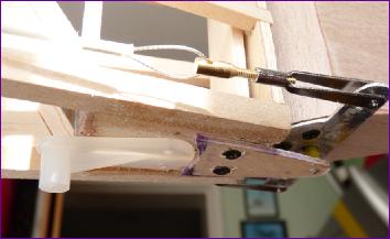
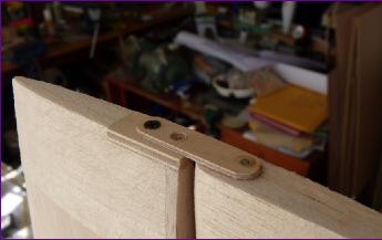
To enable the tailplane to be fixed and removed with the fin in place, I used a dowel and bolt arrangement. A bit of care was needed to ensure that the dowel fixing cleared the elevator horn and linkage. The elevator servo is mounted in the tailplane so that only an extension lead has to be connected when fitting the tailplane.
The plan calls for a second tailplane fixing bolt directly under the front of the fin, as per full size practice. Perfectly okay as a retention system but no good with a fixed fin!
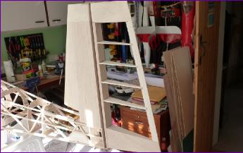
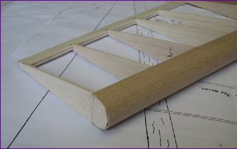
Again I skinned the fin in balsa rather than ply so will have to add the hinge shroud later. However I did stick to the plan when it came to the rolled ply leading edge which was built before adding the ribs. I did spend a fair bit of time thinking how best to tackle this. In the end, I set the jaws of my B&D workmate to follow the taper of the rudder post, applied PVA to the formers, tacked the ply to their centre points with cyano then, using a piece of aluminium angle to keep it straight, pressed the post and formers into the gap between the vice jaws, forcing the ply to wrap around them - a bit like moulding acetate by pushing a plug through a female template. Once the rudder post was level with the top of the vice jaws, the vice was gently tightened and the glue left to dry. It worked surprisingly well.
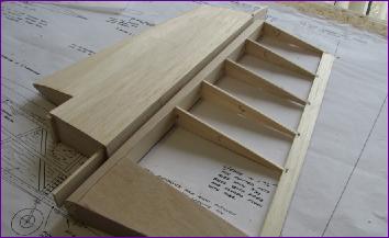
The trailing edge of the rudder was specified as per the wing - 1/64 ply slotted into the ribs then 3/32in balsa pieces fitted each side between the ribs. Instead, I made up the balsa/ply/balsa trailing edge first, as a continuous strip, sanded it to profile and then notched it to take the ends of the (shortened) ribs. This worked very well and if I were building the wings again, I would use this approach there too.
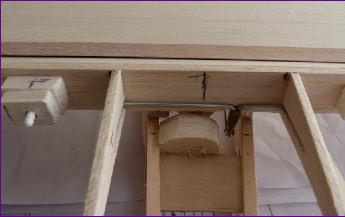
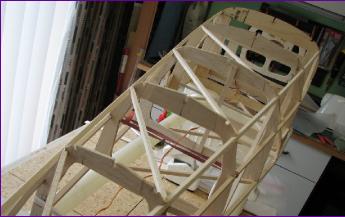
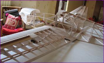
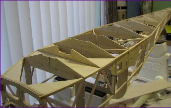
Next up was the top of the fuselage. Access to the insides gets harder after this step so the elevator servo extension lead and rudder closed loop guides were installed before embarking on this stage.
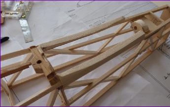
Diagonal struts go in first between the main formers, then intermediate formers are fitted, which have to be notched to fit around the diagonals. Finally the upper stringers and top keel can be fitted.
There is a bit of 1/16 balsa infill immediately behind the cockpit area but otherwise the structure is left open.
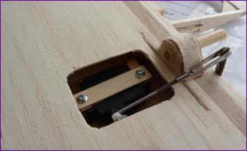
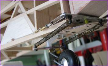
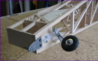
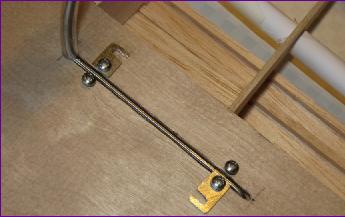
The next three pictures show the prototype 'metalwork'. The upper and lower rudder pintle plates were made from 1/16in ply, as was the tailwheel steering arm. The rudder horn was cut from soft aluminium and the springs were from my scrap box.
Actually, these parts may well have served okay, although the springs were decidedly soggy. Anyway, once everything was lined up and working, I went round to modelling friend Ken for lesson one in sheet metalwork. . .
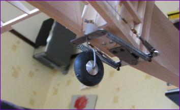
Ken made up mild steel parts to replace my ply prototypes and silver soldered the pintle pins and tailwheel wire to them. Meanwhile, I raided his stock for some beefier springs and a piece of dural to make the mk.II rudder horn.
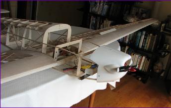
Having got the tailgroup all fitted out, the model was assembled for another balance check, confirming that the likely battery location is around the pilot's footwell.
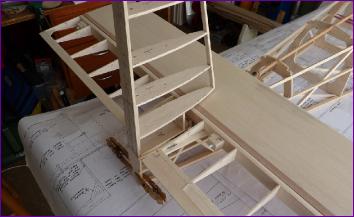
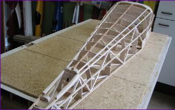
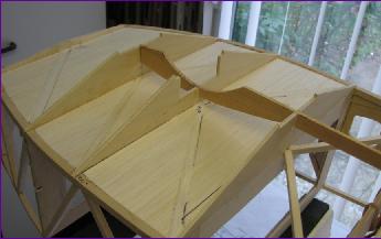
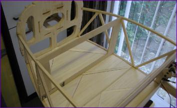
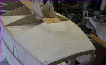
Up until this point the model has sat flat on the board on the lower stringers. However, now I had to turn it over and add the shape to the underside in preparation for fitting the monowheel. The cockpit floor was also fitted at this time.
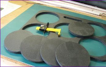
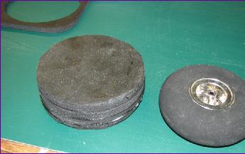
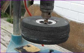
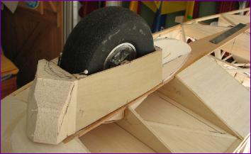
Before going any further with the wheel well, I needed to sort out the wheel itself. The commercial item I bought online turned out to be rock hard so I had a go at making my own from a foam rubber kneeling mat.
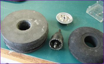
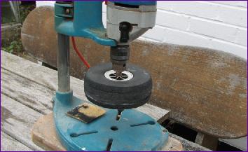
Having run out of contact adhesive, I used RC Modellers' glue to stick the laminations together. This seemed to work okay but when I bored out the hole the following day, the cutter came out covered with fresh wet glue.
That was when I realised my mistake - being water-based, the glue needs air to dry and, apart from around the exposed edges, it wasn't getting any!
Attempts over the next few days to shape the wheel all ended up with the layers delaminating and glue oozing out of the joints. However, eventually we got there and since then there has been no more separation of the layers so I am hopeful that the glue will fully set in time.
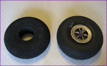
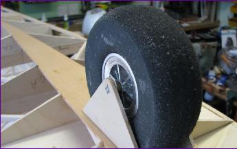
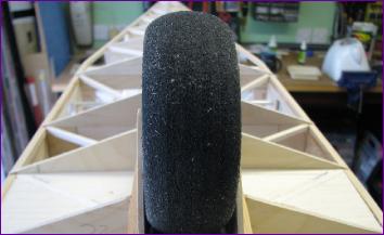
The good news was that I was able to re-use the hub from the commercial wheel. I fitted a 3mm ply spacer between the hub halves to take up the extra width of my wheel. The next step was to see if it would fit the model.
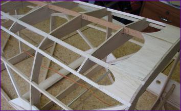
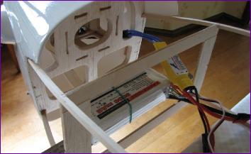
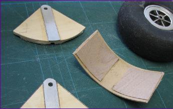
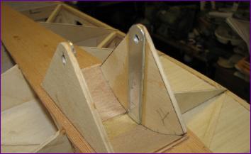
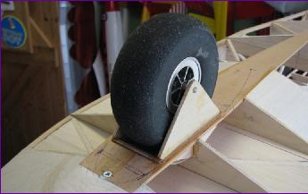
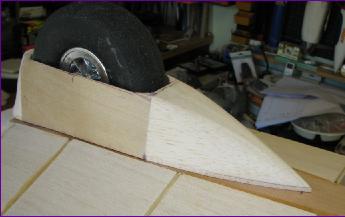
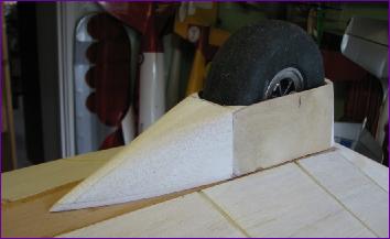
The next few pictures show one of many dry fitting sessions before committing the epoxy in this critical area. axle supports are from 1/8in ply with dural bracing strips and the curved section is specified as 1/16in ply. I made it up from two laminations of 1/32in ply in order to set the curvature. The additional 1/64in ply patches are to help the side plates snap into place in the aperture at final assembly. You can just see some pieces of scrap 1/8in balsa glued to the outside of the side plates to hook under the edges of the aperture in the spruce keel. In the end, everything locked in place nicely.
The wheel fit between the plates can best be described as snug. To be fair, it is not quite as tight as the second picture suggests!
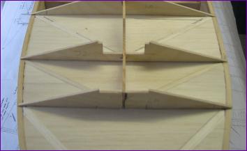
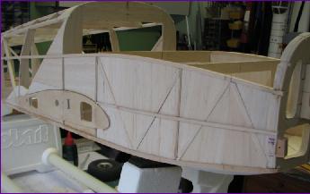
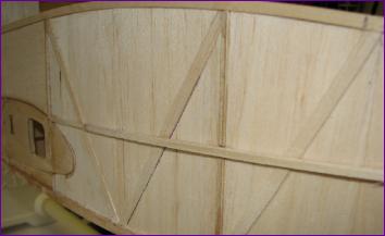
In the intervals between wheel shaping sessions, I pressed on with making the underside noseblock (which curiously has to have a hard point set into it to take a screw retaining the front of the bottom keel) and the infill sheeting on the fuselage sides. Cutting all of those triangular pieces was an exercise in care and patience!
The waist strip which holds the covering away from the infill sheeting is specified as 1/4 x 1/8in spruce but, much like the curved section of the wheel housing, I didn't fancy getting it to cope with the bend so instead used a couple of laminations of 1/32in ply.
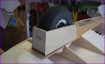
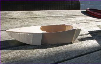
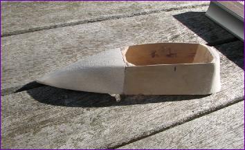
Back to the undercarriage. With the wheel mount at last glued in place, the next job was the fairing. It is suggested that a fibreglass moulding is used for this but there is a note that ply and block balsa could be used as an alternative. Beyond that, you are pretty much on your own.
Two 1/32in ply sides were pulled in onto two simple balsa formers, then I added front and rear balsa baseplates, and finally some rough hewn balsa blocks were glued to the baseplates and formers.
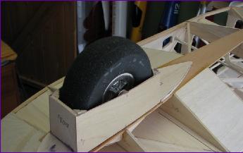
The fairing was located by means of three pegs cut from cocktail sticks and retained by two small pieces of 1/32in ply on the insides of the sides which engage with the ends of the axle.
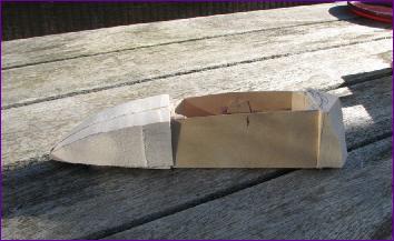
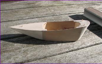
After a fair bit of carving and sanding, it was looking a bit more streamlined, albeit still very boat-like.
When I re-fitted the shaped fairing, the rear section didn't look quite right. There seems to be a bit of a discrepancy between the side view on the plan and the photographs of the full size. Anyway, I had another go with the sandpaper and re-shaped it as in the right hand picture below, which looks a bit better to my eye.
The last two jobs of the month were making the outriggers and beginning to think about the cockpit / battery stowage area, in particular how the battery was going to fit around the pilot's feet.
The outriggers on the full size are apparently carbon fibre so the wires have fuel tubing slid on them to bulk them up a bit. I'm not sure whether this is going to look right but it is easier to cut off the tubing if I decide against it than it would be to try to slide it on after the wires have been bent up.
I did in fact fit the wing tip plates and tailplane tip blocks before the month end, but didn't get around to photographing them. So 62 pictures will have to be enough for this month!