The video on the left shows the mock up being operated from a servo tester via small servo mounted on the front of the bulkhead. This servo positioning was initially intended for test purposes, but in the end, I carried the idea through into the final version.
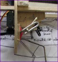
The critical phase for the mechanism is at the midpoint when the end of the operating crank passes close to the leg's pivot point, as shown here. Although the unit worked well with a lightweight wheel, it did need a bit of help from a balancing spring when fitted with a heavier wheel.
Another comment on this version, from the original designer, was that the shock absorbing properties of the u/c would be better if the pivot point was forward of the lowered wheel so that the torsion rod portion of the leg would allow the wheel to swing up as well as back. I was initially worried about moving the pivot point forwards since it would reduce the retract angle from the magic 90 degrees. However, after thinking about the geometry, I suddenly realised that this could actually prove advantageous in that the operating crank length could be reduced. The key thing is that the sweep of the crank and the retract angle must together add up to 180 degrees to ensure that theu/c locks correctly both up and down (Hands up who remembers doing cyclic quadrilaterals in school geometry?!). So, the mk2 unit was drawn up with a nominal retract angle of 80 degrees, the crank swinging through 100 degrees
To check that the throws could be set up the same on the two units, here they are being operated from a Y lead. The mounting bulkhead has been moved forwards and the change in retract angle incorporated. These units can now lift two heavy wheels each without the aid of any balancing spring. However, I did take the precaution of fitting a wheel collet high up on each leg to be used with a balancing spring (or maybe to close the u/c doors?) if necessary.
You can also see that saddle clamp bearings are now used both for the u/c leg and for the operating crank, eliminating the need for any side frames. Those holding the leg in place are fixed with 3mm hex head bolts into captive T nuts so that they can hopefully be removed via the wheel well should the legs need to be straightened.
 The critical phase for the mechanism is at the midpoint when the end of the operating crank passes close to the leg's pivot point, as shown here. Although the unit worked well with a lightweight wheel, it did need a bit of help from a balancing spring when fitted with a heavier wheel.