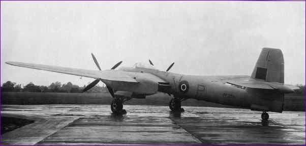
Westland Welkin Project Diary by Trevor Hewson
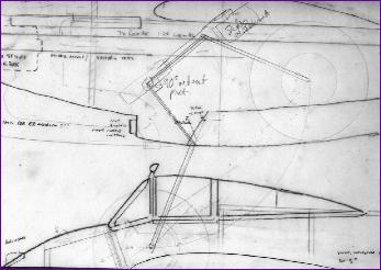
In contemplating what to build after the Rapide project, I couldn't help but notice the two leftover brushless motors and ESCs lying idle on the bench. I had thought of using these to re-motor my P38 but was concerned that the aged airframe may not cope with the extra power. So it was that I started looking round for another twin project, suitable for powering off a 3s LiPo pack through 8in diameter propellers. Clubmate Mike Roach mentioned that he had long ago drawn up a plan for a Westland Welkin of a roughly suitable size, and that he also had a nice book on the full size. I arranged to borrow both plan and book and started browsing. As I studied Mike's plan, I warmed to the Welkin as being a pleasant change from the more commonly modelled WW2 twins. Also, as a fully metal skinned airframe, it was a very different construction project from the Sealand and Rapide which had occupied my building board for the last couple of years. There were of course lots of questions to be answered - What size should the model be? Should I model the Mk1 or the twin seater Mk2 with its long snout? The issue that kept coming to the top of the pile though was the undercarriage. The simplest thing to have done of course would be to leave the landing gear off entirely. The next easiest would be a fixed u/c. Really though, this model cried out for retracts so, before going any further, I put a sheet of tracing paper over Mike's plan and started doodling. . |
||
August 2008 (More on August) I had hoped up until this point to utilise commercial retract units but, after a few enquiries, all the readily available units seemed to be designed for sideways rather than rearwards retraction, which potentially transmits the bulk of the landing shock loads straight onto the locking mechanism.
Several sketches later, and I was ready to bend up a test undercarriage leg out of some fairly soft wire. |
||
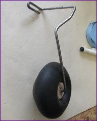 At this stage someone pointed out that Ivan Pettigrew, designer of the Sealand and Rapide, also had designed his own low-tech home made retracts, specifically intended for rearward retraction into the nacelles of multi-engined aeroplanes. Now normally any prospect of mechanical engineering would have me running a mile but Ivan's design seemed to involve no advanced fabrication or machining techniques, just a rather tricky bit of wire bending - and I knew a man who could help me with that!
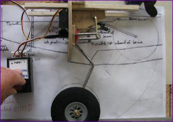
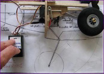
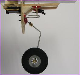
September 2008 (more on September) With the wire leg bent to shape, building up a rough mock up of the mechanism was a fairly quick process. The two pictures below show it with the wheel down and with it in the retracted position.
This crude setup worked well and felt encouragingly rugged in the down position. The secret of the mechanism of course is the 90 degree angle between the operating crank and the hairpin bend in the leg, both in the up and down positions. Having played with this mockup for a few days and discussed it with fellow modellers, I reckoned I had got a good enough grasp of the changes and improvements needed to embark on a 'real' one. (See the detailed September entry for more on this, and for videos of both versions in action).
With two working retracts built, this project was definitely now on, so it was time to build a wing to hang them from. Whilst the retract development was going on, there had been some discussion on the right size for the Welkin. As you might have spotted in the bottom left of the above photos, the eventual decision was to scale Mike's plan up by 5%, giving the model a wingspan of about 61 inches. Apart from hopefully providing a reasonable balance between wing loading and power loading, this also brings the 3 inch wheels shown in the photos into scale.
|
||
 The biggest change though was that this time the u/c leg had to be bent up out of 10swg (about 3mm) piano wire hard enough to take the landing shock loads. I am indebted to clubmate Ken Spokes for his help in forming the hairpin bends in the wire, but I am quite proud of the fact that I managed the remaining bends unaided - and that the two legs match!
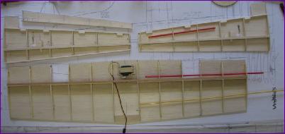
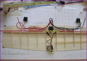 By the end of the month, I had the beginnings of a wing structure taking shape and could start to contemplate the routing of the various wires and control runs. With three servos and two speed controllers in the wing, it seemed logical to fit the receiver there too, leaving only two servos in the fus to connect when the wing is fitted. (No, the tailwheel isn't going to retract!).
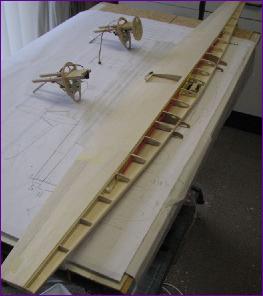
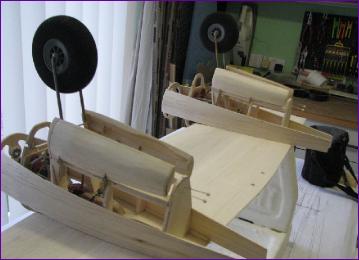
October 2008 (more on October) First job in October was to work out how the nacelles would be secured to the wing. These two pictures show liteply rib doublers, keyed into the spars and extending below the wing to attach to the nacelle bearers. Whilst I hope to get most of the wing built before attaching the nacelles, the leading edge will have to be fitted afterwards, probably with a hardwood section inserted to take the landing shocks from the nacelle.
Eventually though, the three panels started to take shape. The next conundrum is at what point to join the panels together? I would rather work on the nacelles without the tip panels getting in the way. On the other hand, joining the wing panels with the nacelles in place could make it hard to get the dihedral and washout angles right. . . |
||

 Having sorted the nacelle attachment question, the rest of the month was spent on the wing structure. So far this has gone fairly smoothly, albeit very slowly.
November 2008 (more on November)
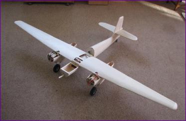
Just dry fitting the panels together shows off the unusually high aspect ratio for a plane of this type.
This picture also shows first thoughts on position of the rudder and elevator servos. As shown, the servo leads just reach into the wing fixing bay, and a straight elevator pushrod can still be used to reach the raised tailplane (see detailed November diary entry for more on the tail configuration.)
After sheeting it all in, the elevators and tailplane were taped together and the tip blocks glued on and shaped. A strategically placed piece of tape meant that, after a few strokes with the junior hacksaw, the elevator could be separated again, complete with its balancing tip.
It's nice when things go to plan! |
||
 After sorting out the arrangements for the dihedral braces, I went ahead and sheeted the aft sections of the wing panels. This stiffened them up pretty well so I opted to leave the final joining up of the panels till later and left the front top sections were open for now.
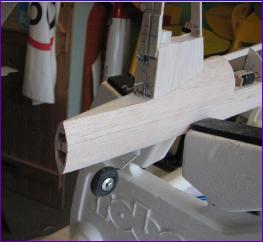
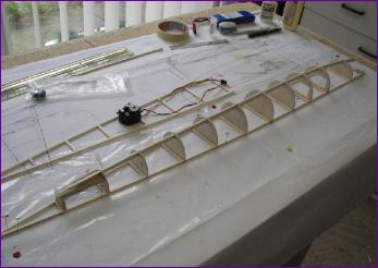 So now to the fuselage. Two horizontal crutches were built on top of each other before the lower former halves were fitted to the bottom crutch. I extended the keel forwards to keep the option open of making the MkII version, final decision to be made after an assessment of cg/battery position.
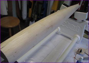 Once the tailwheel mounting was sorted, the underside sheeting was applied and it was time to move on to the tail surfaces themselves.
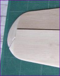 The fin has to be built in situ to enable the tailplane to be slid into position, so it seemed sensible to get as much work as possible done on the tailplane first.
December 2008 (more on December)
You can read more about the construction of the fairing in the separate December diary page, but eventually it all came together as you can see in the picture below left . The rear fairing section is removable at this stage because I will want to cover the elevators before glueing the hinges in place.
As well as doing a balance check to get an idea of where the battery might end up, I took the opportunity to do a first weight assessment too. As pictured, the model weighs 2lb 11oz so an AUW of 3.5 - 4lb looks to be achieveable. |
|||||||
|
|||||||
 Before fitting the tailplane, the rear end of the fuselage and lower fin were sheeted in. The rudder linkage was finalised at this stage too.
 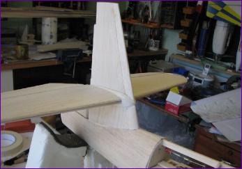 There then followed a long process of fiddling around with the bullet fairing before finally fitting the tailplane and building the upper portion of the fin.
 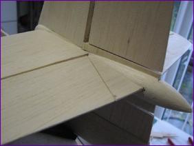 With the tail group more or less sorted out, I sheeted in the rear fuselage and moved forward to the wing fixing arrangement.
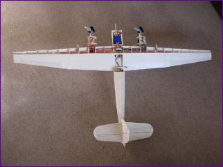 Then the retract units were glued in place and at last the model could stand on its wheels for the first time.
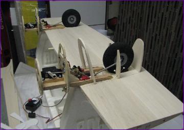
January 2009 (more on January)
The top surfaces of the nacelles proved to be more problematic than the undersides, and I have had to resort to the use of considerable quantities of filler (Oh the shame!)
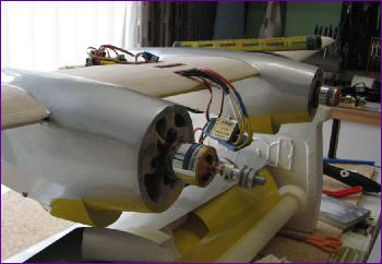
Anyway, for the moment, it all seems to work, the motors turning 8 x 6 APC e propellers at around 10,000 rpm for a current draw of 2 x 15a off a 3s 3700mah LiPo battery.
I can put that off for a bit longer though by making a start on the noseblock! |
||
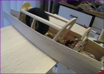
 Once the doors were working okay, I plucked up the courage to sheet in the undersides of the nacelles.
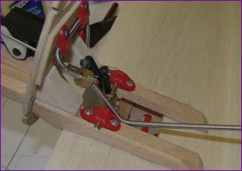
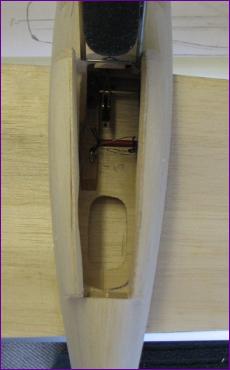 Although it should theoretically be possible to get the undercarrriage legs out should they need to be straightened, the rest of the retract mechanism becomes pretty well inaccessible from this point, as you can see from the picture on the left.
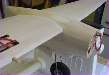 The motor cowlings were next (pictures on the
 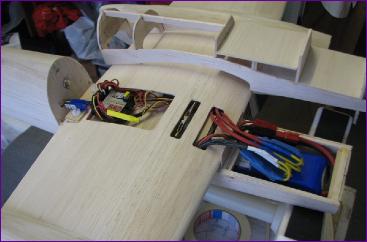 As you can see, I sorted out the wiring at this stage too, just to make sure that the hatch would fit over it all. The piece of yellow heatshrink near the receiver is joining the 5v positive feed from the right hand ESC BEC to the Y lead feeding the retract servos. This should mean that any retract malfunction will not affect the Rx and flight controls which are fed from the left hand ESC BEC. However, I suspect that a BEC shutdown might shut down the corresponding motor which would not be too helpful.
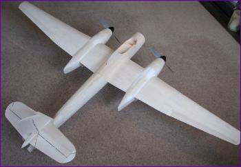 By the end of the month the top section was complete, apart from the noseblock and of course the cockpit itself. I need to find one or two pilots (The MkII had a second crew member behind the pilot, facing to the rear) before working out what to do about the cockpit canopy. I bought a replacement canopy for an ARTF fighter of some sort in the hope that it might be possible to cut it down to fit, but it isn't looking too promising so I may well have to make a plug and have a go at moulding one from scratch.
February 2009 (more on February)
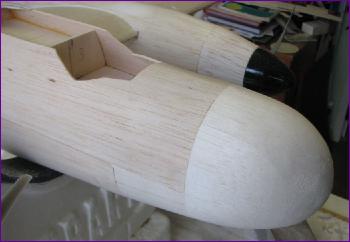
Things started well enough with the noseblock coming out really well. Then though it was time to embark on the challenge of the canopy. I carved a plug and tried to draw-mould a canopy (see separate February page for details). The first attempt was came tantalisingly close to success.
It did though result in a useable rear section and, since the front and side screens are flat, I did contemplate building the canopy up in sections. However, clubmate Mike Roach was giving good reports of Vortex Vacforms so I wrapped up the plug and sent it off. The pilots (from Pete's Pilots) were also handed over to Mike for painting.
In parallel with this I carried on preparing the airframe for covering. This seemed to be an endless task. Each time I thought it was done, there was another part that needed filling or another dent that appeared overnight. Eventually I called a halt, had a big tidy up and got out the covering iron.
Hopefully March will be the month when it all comes together. |
||
 Most model building projects seem to go through a slow phase - and, for the Welkin, February was definitely it!
 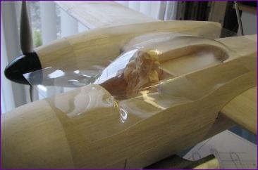 Unfortunately, this was as good as it got. After giving up on the draw method, I tried heat-shrinking a plastic bottle round the plug. Again this was only partially successful.
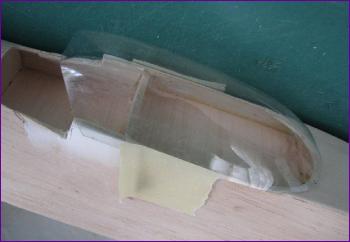
 Visible progress at last!!
March 2009 (more on March)
Here you see the canopy fitted over the two occupants. The pilot has an instrument panel scanned and re-scaled from a photograph, whilst a couple of blocks of balsa wood simulate the instruments for the radar operator.
Although the model is far from finished, there was little now standing in the way of a test flight - just the small matter of a range test. . .
Unfortunately the range test was a total failure. Even switching to HobbyWing ESCs, which fixed a similar problem in the Rapide, effected only a minor improvement.
After pondering this for a bit, I fished the aerial wire out of its tube (running inside the starboard wing) and routed it out to the top of the rudder. This improved things considerably, so it was off to the flying field at last.
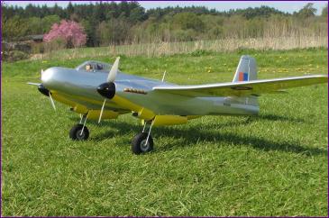
The picture on the left was taken after a successful maiden flight. The flight went well but, with no cooling provision for the ESCs or for the motors, it was kept very short. Nothing got unduly warm though so I will try to increase the duration of subsequent flights gradually and see how it goes.
Meanwhile, there is the matter of the roundels, exhausts and various other details to attend to. |
||
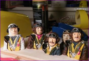 Mike got the pilots painted very promptly and even offered me a choice of crew members. As you can see, he did a good job on them.
 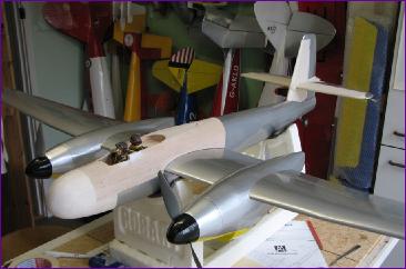 Meanwhile, I was making steady progress on the covering. Some of the compound curves posed a bit of a challenge and the tailgroup was every bit as fiddly to cover as it was to build.
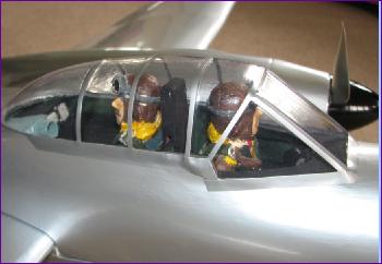 There was a bit of a wait for the canopy to arrive but when it did it was well worth waiting for. Although not optically perfect, it is a much stronger item than I would ever have managed on a DIY basis.
 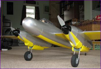 Only when I looked at this photograph did I realise that the yellow covering was missing from the underside of the nose!
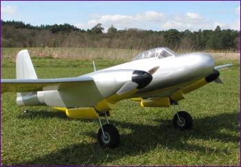
April 2009 (more on April)
The final job was the exhaust stacks. Full details of how these were fabricated are in the April Diary entry. Whilst they aren't perfect, I'm quite pleased with the general effect.
So, that's about it. All that remains is to get out there and try to put more flights on the model than the full-size ever recorded!
My thanks to Mike Roach and Colin Arnold for some of the photographs.
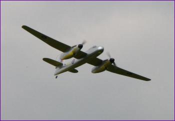
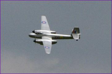
The Video Clip link below shows some snippets of this month's flying
|
||
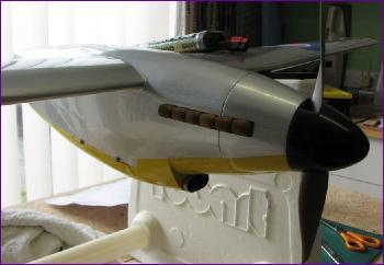
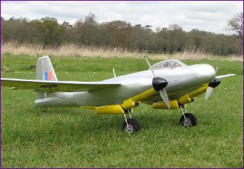 The first job I tackled was the chin radiators. These were made out of Plasticard, the hardest task being to get the thin rim to fit snugly around the backplate.
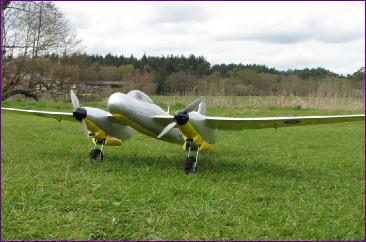 Because of the white in the roundels, I did a swap with Mike, exchanging some peel 'n' stick transparent vinyl for some white label material. This produced a matt finish, to which a coat of fuel proofer was applied to avoid water damage.
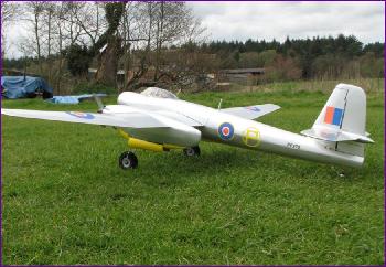 The yellow 'P' prototype marking is cut from solartrim and the serial number is rub-down lettering. Although they are barely visible in these pics, I also drilled out the canon flutes on the underside of the nose. These provide a trickle of air over the ESCs, but the motors are still uncooled. So far though, they have shown no signs of getting particularly hot.
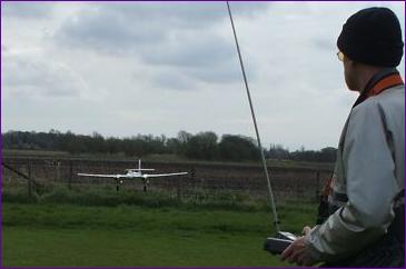 The Welkin had a few more flights in this condition and is proving to be a very nice plane to fly. I am especially pleased with the way it holds its line and speed on landing approach, with the result that so far the retracts haven't had a real pounding.