Kwik-Fli IV-40 part II


(click here to return to part I of this diary)

November 2017
Having cut out the fuselage sides, the next step was the ply doublers around the wing seat area. Once I'd marked out where the formers and battery tray were going, the doublers were extensively fretted out. This halved their weight - and saved some glue too!

0.8mm ply is a bit thin for my table fretsaw so the doublers were tacked together with double sided tape so that they could be fretted out as one.

The doublers and triangular strips were applied to the inner faces of the sides (not forgetting the balsa doublers around the tailplane seat). Then some formers were built up and the sides joined upside down over the plan.

The firewall needed a bit of extra thought. It had to be moved forwards slightly from the drawn position in order to accommodate the length of the retracted noseleg. Also the mounting beams for the nose retract were to be let into the firewall and were in danger of clashing with the motor mount. Eventually though, I was happy that it should all fit and made up the firewall out of 3mm ply, with 3mm ply doublers around the motor and retract mounting points.

Before glueing the firewall in place though, I felt the need to prop the model up on its wheels to be absolutely sure that the noseleg was long enough!

Once happy with this, there was then a long process of cutting out card templates and general fiddling about to sort out the details of the nose retract installation. As you can see from the pictures, it's a snug fit!

Up until this point, I had assumed that the nose steering servo would have to go on top of the wing but I was pleased to find that it could be squeezed into the retract bay. The model was once again set on its wheels to get an idea of how much steering lock might be required - rather less than I thought in fact, due no doubt to the short wheelbase.

Out with the cardboard again for more templates in order to fabricate a hatch. I'm not sure yet whether I'll bother with a leg fairing to close off some of that weird shaped aperture. The hatch is from 3/16in balsa laminated in situ onto 1/32in ply. This sets the curve into the hatch for a better fit and provides a ply base for the screw heads to bear against.

Last job of the month was the installation of the rudder and elevator servos and associated snake runs. The rudder is a conventional Sullivan nylon snake, the elevator is a 3mm carbon pushrod running in a snake outer - I'm not a big fan of nylon snakes for elevator linkages, since they can lead to trim changes with temperature.

That's it for another month. With any luck the woodwork should be just about finished in December, and I'll have to start thinking about colour schemes and canopies - oh joy!

December 2017

Well, I did get a bit more woodwork done, but a trial balance exercise established that, in contrast to the prototype which needed lead in the nose, my model is if anything nose heavy - without the battery! This implies that, instead of sitting on the tray under the hatch, the battery will have to be 'posted' through F2 to sit on top of the wing.

However, I've been caught out before by how much the cg can shift after covering so I opted to get as much of the covering done as possible before finalising the battery stowage arrangements.

Before getting the iron out though, there was one more thing I wanted to try. Following a tip on a forum, I'd ordered a multiway connector kit from Banggood.com. For just over a fiver, this consists of what looks like a lifetime supply of connector housings in all sizes from singles up to 12-way. The crimp inserts are provided too but the thing that attracted me was that the housings are compatible with the inserts used in standard extension leads.

So, as you can see in the pictures, I was able to take three extension leads, pop the inserts out of their 3-way housings and push them into 10-way shell to make up a 9-way connector. This means that the two aileron servos and the (Y-leaded) retracts can all be connected in one operation as the wing is fitted.

The only worry I have with this system is that, unlike normal servo connectors, there is no protective shroud round the pins, leaving them rather vulnerable if the connector is left loose in the fuselage. I'll re-visit this issue later when finalising the installation.

So to colour schemes. After looking at what film I had in stock, I decided to base my model on some pictures I found of the now-defunct E-Flite Leader 480.

Starting on the underside of the wing, I found that I had enough white trim to do the stripes so covered the entire underside in blue, before cutting out paper templates for the white stripes. At this point I got a phone call from a clubmate asking if I had a bit of white trim to spare!

His neeed was greater than mine so the white trim was traded for some chequered Fablon. Once the red was added, it looked rather striking - the upper surface is going to be quite dull by comparison!

Next, the top of the wings were covered in white. Because of the open structure, a substantial overlap between the white and red film was unavoidable. This is a sure-fire recipe for trapped air bubbles so, after a bit of forum discussion, I tried an experiment and perforated the area of overlap with a pin. Apparently there is a tool available which will do a neater job - and no doubt quicker too - but this information came just too late to include it on my Christmas list, so jabbing with a pin it was.

I have to say, this method worked better than I'd dared to hope. It's only taken me thirty years to discover it!

The blue on the top of the wing really needs to be from trim or vinyl rather than film, so that it can be floated on, so that is held due to a stock shortage. It's at times like this that I miss the late lamented local model shops. Anyway, meanwhile, on with the tailplane. . .

The rear underside of the fuselage was covered in blue and the sides with white but there was not much more I could do until the top of the fuselage was completed so it was time for another balance check. Unfortunately this confirmed that the model was still nose heavy, so the battery would indeed have to be located as far back as practicable. At least I had left the top of the over-wing section of the fuselage off, so access to build the necessary battery box was a lot easier than it would otherwise have been.

Once I was sure that the apertures in F2 and F3 were big enough, a 'roof' was fitted between them. An extension to the battery floor through F3 was also fabricated and fitted. Having grappled with changing battery stowage arrangements through the NiCd/LiPo eras, I took the precaution of making this floor removable.

The two pictures below show the largest of my 3300mah 4s packs in situ. I have other packs which are smaller so a selection of spacer plates may be needed in order to stop them rattling about. A forward stop of some sort also has to be devised but at least at this point I felt confident to close off the top of the fuselage.

After fitting the remaining turtle deck piece, the hatch was constructed. It is retained by ply tabs at the front and two pairs of magnets at the back.

With the magnets in the fuselage glued in place, I pressed the matching pair into the recesses in the hatch for a trial fit. The hatch snapped nicely into place and when the hatch was removed, I fully expected to see the magnets firmly attached to their partners. However, they remained in the recesses of the hatch, despite not being glued in. I'm now faced with a dilemma as to whether to dig them out in order to glue them back in or leave them be unless and until they come adrift.

After a session with the sanding blocks, it was clean up time again and then out with the covering iron once more.

So, as the month (and 2017) came to a close, there's not really a lot left to do. However, at this point in a project I make a list of all the outstanding jobs, if only to ensure that nothing vital gets forgotten (such as gluing in control surface hinges!) The problem is, each time I go to tick something off the list, I normally think of a couple of more things to add to it!

In a couple of days though, the list should start reducing and so, weather permitting, next month's diary entry should include a maiden flight report.

January 2018

I was surprised how much the addition of the simple blue trim livened up the appearance of the wing.

The underside is a good contrast but, those wheel wells suddenly looked a bit naked and vulnerable so they were treated to a coat of paint before going any further.

Finally, those long put off jobs of the battery retainer and the canopy just had to be tackled. a clubmate found a canopy for me of rather uncertain vintage (I don't know whether it was pale green initially or not!). This was painted black on the inside before fitting.

After a bit of head scratching, this is what I came up with by way of a battery retainer. It works well but clearly there is a limit to the variations of battery length that it can cope with.

With the markings applied (courtesy of Tim at ModelMarkings.com), it was out into the garden for one more photoshoot.

The wait for suitable weather for the maiden flight was thankfully not too long so, batteries charged, transmitter programmed, it was off to a fairly cold and soggy flying field - where I felt the need to take another couple of photographs!

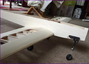
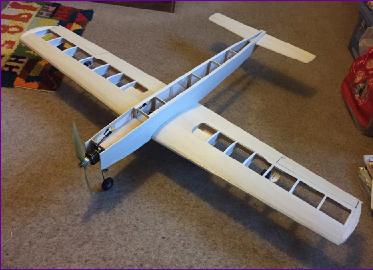
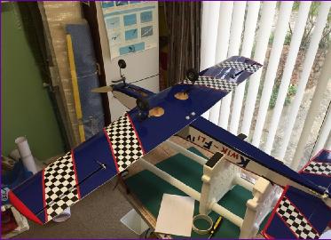
The maiden flight was happily uneventful. No significant trim changes were needed and the control throws, although not optimal, were comfortable. There was no trace of the famed 'Kwik-Fli Dance' and the handling was pretty much as expected. I did though reach the end stop of the elevator travel on flairing out for landing, so the elevator throw was increased slightly for subsequent flights. It is possible that the cg could come back a bit further too, but I'm happy with it as it is for now.

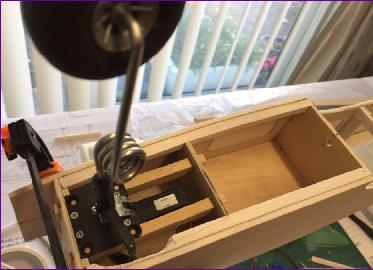
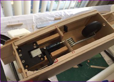
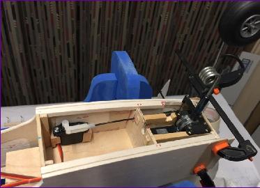
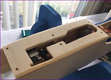
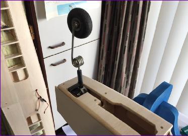
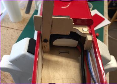
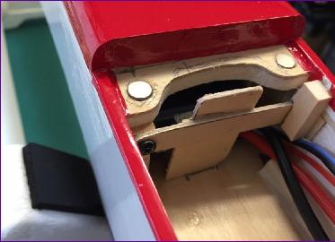
The only problem to emerge on these early flights concerned the nosewheel retract. Although it seemed to retract okay along with the main gear, it had a habit of coming back down again. There was no sign of any mechanical obstacle so my thoughts turned to the electrical side of the operation. I believe that these electric retracts (from HobbyKing) don't use limit switches to detect when the leg has reached the end of its travel. Instead I suspect that they rely on detecting the surge in current when the motor stalls. The maingear acts a bit faster than the noseleg so I wondered whether the surge in current accompanying the arrival of the maingear against their endstops was causing enough of a voltage drop to confuse the nose unit.

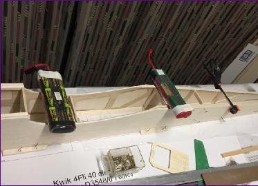
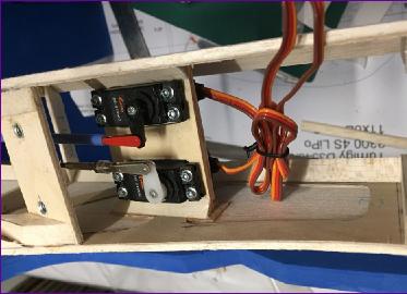
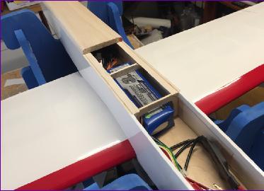
The retracts are powered by a separate uBEC of nominally 5a capacity, although looking at how skinny the wires are, I've always been a bit sceptical. Anyway, to eliminate this effect, the nose retract was plugged into a separate receiver channel so that, although it still operates from the same switch as the mains, it can be delayed by a couple of seconds so that it can then have the power supply all to itself after the mains have done their thing. Since making this change, the gear has operated faultlessly.

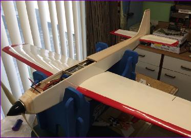
I've now chalked up 9 flights with the Kwik-Fli and have got it pretty much dialled in to my liking. I look forward to a long and rewarding relationship!

This will probably be the last diary entry but if/when I get some airborne pictures and/or video, I will add them to the site, so keep an eye on the 'Latest News' page.