Each Way Bet - The Full Story
Mike's reply to my e-mail confirmed the death of the Project X configuration: "So the real aim is not to solve the problem of reversing the direction of flight (we seem to have done that, albeit as a flying wing with a body), but actually to solve a more dificult problem, which is to build an aircraft that will fly both forwards and backwards, as described in your April Fool article. I think that to do this you will have to stick more closely to your original concept."
There then followed a series of brain-storming e-mails, with various proposals, ending up with the following (May 2001):
Mode 1. Normal Flight
Mode 2. Canard Flight Simple! No retracting/extending fins, no variable 'V'. Just the small matter of the shifting c.g.
I got quite excited about this new approach and Mike and I agreed a division of work - he would cut some foam wings and I would tackle the fuselage and the avionics. However, six months later, we had progressed no further and in January 2002 Mike reluctantly withdrew from the project. Whereas Mike, like Peter eight years earlier, appeared to be completely cured from the Project X obsession, I merely went once more into remission. This time for six years.
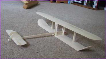
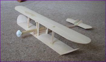
In the meantime a lot changed: Not only was I now flying electric powered models almost to the exclusion of slope soarers but indoor radio control had suddenly come from nowhere to be accessible to everyone. Most significant of all, we had discovered the joys of Depron! This foam sheet material meant that anything from scale models (e.g. SE5a) to the weird and wonderful (e.g. Und Nu) could be put together for very little investment. Also, during the Winter of 2005, I tackled another really offbeat project, David Stanger's pioneering Canard biplane which, for reasons of scale fidelity, had a fully built up structure. Nonetheless, the fact that this unlikely-looking configuration was perfectly stable, even with small vertical fins mounted on the canard, inevitably stirred up memories of Project X, and it was time to bring the concept into the new age of indoor radio control - and the economies of Depron. The challenge now though was all the greater - reversible flight now had to be achieved within the confines of a building. |
||
|
|||||||
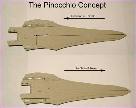
The surprising thing about this was that there was no immediate sign of yaw instability in either flight direction. Just as well really because, with the new lightweight indoor concept, we really wanted to avoid all the complexity of gyros etc. In my humble opinion, the Pinocchio concept remains the most elegant of the many incarnations of this project but unfortunately it fell at the first hurdle as soon as I got my calculator out. Here is an extract from the e-mail exchange between Mike and myself:
Trevor: I just did a few quick sums on the cg shifting. I reckon the cg will need to shift about 6cm to change flight modes. If the moveable bit amounts to one third of the all up weight, this means that it would need to move 18cm, which is a lot more than I had in mind!
Mike: 18cm is indeed a very large CG shift. Have you come to any conclusions as to the mass of the moving part? Might the wing move as well, an a sort of counter-baance way?
Trevor: The Stanger needed the cg just in front of the l.e. for canard flight so, to move from there to 1/3 chord for conventional flight means a c.g. movement of at least 2/3 chord. That's where my 6cm figure came from. Working on an AUW of around 200g, I estimated the weight of the moving section as follows: Motor 20g, battery 23g, ESC and cables 12g, 1 servo 6g, prop and depron 10g; Total about 70g, i.e. 1/3 of AUW. Hence to achieve the cg shift of 6cm, this moveable section would need to shift three times as far. I initially dismissed your suggestion of moving the wing as just more complication, but I am now considering going to the other extreme of moving ONLY the wings. After all, what we are really looking for is relative movement of the centre of mass and the aerodynamic centre. Here goes with a bit of verbal drawing: Biplane wing, with two outboard depron interplane struts as on all the Ultimate models. Now add two more interplane struts in the middle, with a 3mm gap between them, through which the fuselage fits. Pin the wings to the fus with four pegs through this pair of central struts, then cut slots in the fus to allow these pins to slide fore and aft. This opens up other possibilities. In particular, if the slots are curved, the rigging angle of the wing can change as it slides. Of course, this movement would have to be servo driven - the original inspiration of a propellor-driven telescopic fuselage is long gone!
Mike: I'd be interested to know what motor you plan on using.
Trevor: I had been looking at the Robotbirds C22-16-25. However, I am still keen on using the four bladed prop arrangement (one 2-blader facing each way), and the maximum prop quoted for this motor is 8 x 4 two bladed. Having just looked again, maybe the HCS 40W/3 or 1300kv pole and stator motor (also from Robotbirds) would be a better bet. Think I'll carry on musing and doodling for a bit longer!
True to my word, a week or so later, I e-mailed Mike the following doodle:
I also went ahead and ordered a motor, propellers, servos and other bits and pieces, just to make sure there could be no turning back this time..... Part Three
|
|||||||