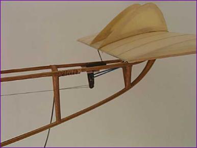
Stanger Biplane - Part 2 After pondering the cg problem, I decided that, much as I liked the simple, direct linkage between the foreplane and servo, I really ought to move the servo back to the rear. As well as hopefully fixing the balance issue, this would also tidy away some of the unsightly wiring which looks so out of place on what is supposed to be a model of a free flight aircraft. While doing this, I took the opportunity to shorten the servo leads and mount the elevator servo, receiver and speed controller on a single piece of balsa positioned beneath the yet -to -be -constructed dummy engine. The servo now pulls down on the rear of the foreplane via a bellcrank and a single strand of cotton. Instead of completing the closed loop, there is a rubber band attached to the bellcrank to provide the return action. I am hoping that eventually I will be brave enough to rely on the lifting force generated by the foreplane to maintain the tension in the cotton, and dispense with the rubber band.
My first attempt at the dummy engine used part of a 35mm film canister for the crankcase and some cardboard tubes for the cylinders. I found a couple of plastic caps to fit on the top of the tubes as cylinder heads and even got as far as linking them with a piece of fuel tubing as an inlet manifold. At this point though, the assemblage was beginning to feel a bit heavy, and I hadn't begun to think about fuel tank, ignition wiring, valve gear etc., so I put it aside and forgot about it for a week or so. Mike Roach has always been a strong advocate of pink foam for carving foam detail such as this and he certainly did a good job with the floats for my Walrus. My efforts though usually end up with me covered in a mass of electrostatic beads of foam, holding an unrecogniseable irregular shaped object with a surface finish resembling a lunar landscape. Nonetheless, I decided to give it a go. It wasn't long before the basic shape began to emerge, but it also wasn't long after that that I started to run into the usual difficulties and I came close to abandoning the whole exercise. In fact I did abandon part of it in that my efforts to shape the cylinder heads came to nought and I eventually fitted bits of balsa around the tops of the cylinders instead. Engine mountings were made from balsa, camshaft mounting plates from 0.8mm ply, cylinder head retaining rods from 1mm carbon fibre rod, the inlet manifold from the outer sheath of some telephone cable, the fuel line from one of the wires from said telephone cable, and the fuel tank from two cones of A4 paper and a circular base of balsa. Slowly, I realised that if I put enough work into the various bits and pieces around the periphery of the engine, the more it would distract attention from the lumps and bumps of the main 'casting'.
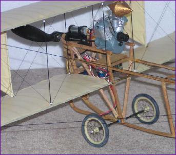
Whe addition of spark plugs, distributor and cables, camshaft drive gears and output shaft, the time had come to paint the whole thing and fit it into the model. Truth be told, I had painted bits of it many times over by this stage, interspersed with fits of filling and sanding to try to smarten up the surface finish of the pink foam. As you can see from the picture, it is still pretty rough, so just imagine how it started out - If you want tips on modelling from pink foam, see Mike, not me! In spite of all the imperfections, there is no doubt that the model looks better with the dummy engine than without and, as Mike pointed out, it is an important talking point with this model, since the hand-built engine was such a major part of David Stanger's achievement in the first place. There are a few other engine-related components visible on the photographs, whose precise role by no means clear. However, these are all well forward of the wings so, with the dummy engine in place, there was no longer any excuse for further delay in tackling one of the other much - dreaded tasks, the rigging wires. Unlike the engine, which had proved every bit as difficult as feared, the rigging turned out to be one of those jobs which, once you steel yourself to make a start, goes far better than expected. It didn't seem like that at first though. I had slid a couple of pieces of tubing onto each interplane strut (you can see two of them on the above dummy engine picture), the idea being that I could simply loop the rigging wire (actually black button thread) around the strut and then slide the tube up the strut to secure the thread against the wing. I hoped that this would give me some scope for minor tension adjustments before the tubes were finally secured with a drop of cyano. The first flaw in this plan became evident as soon as I had tied my first piece of cotton to the first strut - the tube slid up the strut to about 1cm below the upper wing but was reluctant to go any further. Grasping the strut in a pair of pliers, I put the points of my tweezers below the piece of tube and tried to ease it upwards. What happened next, I'm not quite sure. All I know is that suddenly I was staring at a hole in the lower wing covering, two disengaged strut ends waving about and a detached wingtip - and the tube was still in the same place! Cursing myself for such clumsiness, I stuck everything back together and, before resuming the rigging, went around all the struts scraping off any glue residues to ensure that the tubes could slide into place without resorting to undue force. Happily the rest of the process went as planned with no further injuries to model or pride.
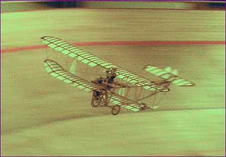
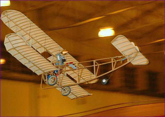
With the addition of some spoked wheels and replacing that orange prop with something a little more in keeping with the period, I think this model is now beginning to look the part. (the last two pictures will enlarge). I will try to add a bit more to this article after the model has flown a bit more but I must say that this has been a most rewarding project. Apart from the satisfaction of seeing something a bit different take to the air, my admiration for David Stanger has grown with each problem I have encountered, realising that the challenges and unknowns that he faced were orders of magnitude greater than any of the challenges that I had to overcome in producing this scaled down replica. And the thought that he committed all his hard work - all seven feet and ten pounds of it - to the air with no means of control and every prospect of its total destruction... well, at least I now have a better appreciation of the debt we owe to Mr. Stanger and his fellow pioneers. Stop Press: First flying picture and video clip added!
..and an even better flying picture by Spike Spencer:
|
||
 I had hoped that these modifications would enable the battery to be re-positioned over the main wheels but was astonished to find that it needed now to be even further forward to offset the cg movement brought about by re-locating the elevator servo. I briefly contemplated re-instating the extension shaft but decided that this could put me back to square one and it would be better to get on and add the dummy engine and other scale details, then look again at battery stowage options later.
 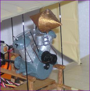 By the time I came to do the camshaft, pushrods and rocker assemblies, I was beginning to enjoy this 'project - within - a - project'. There is no doubt that I am generally much happier glueing bits and pieces on than I am carving lumps off - which is probably why I have always preferred built-up structures to foam or fibreglass mouldings.
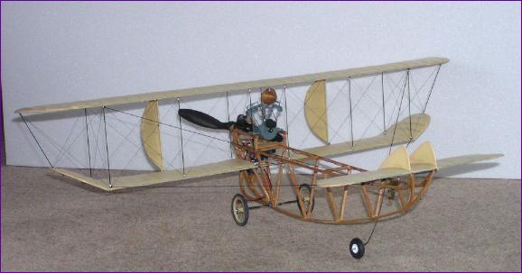
 From the photographs of the original model it is clear that the wing tips were braced to the front of the fuselage. Having been impressed with how the interplane rigging tied the wings together aesthetically as well as physically, I felt that I wanted to add these bracing wires too. However, the scope for breaking the model by snagging these wires during normal handling was a worrry, especially in the light of my recent mishap with the rigging. In the end, since there was no structural need for these bracing wires, I opted to use shirring elastic.