|
   
Dakota Tales
by Trevor Hewson
(adapted from a series of articles originally appearing in Sloping Off - the newsletter of the Christchurch and District Model Flying Club and subsequently published in Electric Flight U.K., the journal of the British Electric Flight Association)
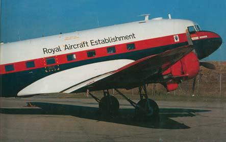
The Portpatrick Princess, pictured at Farnborough
I have always liked the DC3 (aka Dakota, Gooney Bird, C47 etc.), but I would have a hard time explaining exactly why. When trying to think of a realistic subject for electric flight with a retractable undercarriage, it wasn't long before the Dakota came to mind. One of the main attractions was the fact that there are no undercarriage doors to bother with.
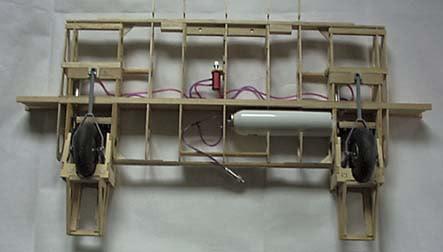
Centre Section showing Retract Installation
Whilst on holiday in the USA in 1998, I got to look around a rather battered specimen and discovered that the retract mechanism itself was in fact far from straightforward. The wheel swings up forwards, pivoting on the rear attachment point, the main leg folding in half at the knee, so to speak. This was enough to put me off the idea, and I started to look for another subject.
Twelve months later, I had still not made my mind up and then, in the June 1999 edition of Radio Control Scale International, there was a review of the TopFlite DC3 kit, for which custom retracts were available. I had inspected one or two TopFlite kits during my quest and they are definitely builders' kits. The wood selection was also better than many US kits I have seen - an important consideration when thinking about electric conversion.
I was tempted to order the kit via the internet ($220 as opposed to £270!) but felt that I ought to try to get to see what I was buying. I eventually tracked down a kit locally and, within a matter of minutes, I was in the shop spreading bundles of wood all over the counter. Not very much later I was staggering out of the shop with a rather large box into which had been added a pair of retracts and a 'Robart Air Kit' which I apparently would need to make them go up and down.
The TopFlite DC3 is to 1/14 scale, spans 82.5" and is designed to be powered by two .25 to .40 2-stroke engines or .40 to .52 four strokes. The weight range given is 8lb to 10lb. The RCSI review model was powered by two MVVS .40s. After discovering that the take off run was about ten feet, the reviewer concluded that two .25s would have been more than enough! Unfortunately he doesn't say what weight his model came out at.
Weighty matters
I assumed that the main sources of weight variation would be engine size and whether or not the optional flaps and retracts were to be fitted. Since I intended to use both flaps and retracts (that was after all why I was building the model in the first place!), my scope for coming in below the upper limit seemed pretty limited. Then of course there is the small matter of the battery.
I reckoned that 24 cells (i.e. three 8-cell packs) would weigh 3lbs, but that, somehow, somewhere I could save one pound, giving me an all-up weight of around 12lb. Now it's time to get out the rule book. The popular 50 watts per lb rule works out well - 24 cells drawing 25 amps gives us 600 watts, which, at 50 watts per pound will fly our 12lb aeroplane perfectly. Next we need to find some suitable motors.
Whilst browsing through my collection of motor information I came across an article by Matthew Orme in which he suggests an alternative rule of thumb - One cell for every 50 sq. ins of wing area. A glance at the box lid shows the wing area of the DC3 to be 750sq. ins, so this suggests a cell count of 750÷50=15. Now, I know this is not an exact science but there is a lot of difference between 24 cells and 15, 18oz of battery weight for a start!
It wasn't particularly hard to work out why these two rules were giving such different answers and soon I was doing the sum which I should have done at the outset - the wing loading. My 24 cell, 12lb approach would result in a wing loading of 37oz/sq. ft. Matthew Orme had assumed a much more sensible figure of between 20 and 25oz.
The message from all of this was clear, if unpalatable: Either get the weight back nearer to 8lb than 12lb or expect the DC3 to fly more like a fighter than an airliner.
Trying to think positively, if we could get down to the 8lb to 9lb range, the model would probably fly on 16 cells. Two motors in series would be working on 8 cells each, so we are now talking about nothing more than a powerful 540 or 600 size motor with a suitable gearbox.
Gear Up
Gearboxes must come a close second to weight on the electric modeller's worry list. In this case there is an added problem. The engine nacelles on the DC3 are very close to the fuselage, limiting the prop diameter to 10". Three bladed props are therefore recommended and will be more true to scale anyway. This does mean though that there is little scope for tuning the drive system by changing the prop size. I therefore felt that I needed a gearbox with a good range of ratios that could easily be changed retrospectively. The MEC Superbox seemed to fit the bill and is very light, so now we can return to the subject of motor choice.
Power Up
Doing the 50 watts per pound sum again on an all-up weight of 9lbs gives us 450 watts. I therefore needed to find a 540 size motor capable of taking 220 to 250 watts of input power. One motor that would definitely do the job is the WEP Turbo 10. This is a very hot (14 turn) motor and is designed to take this sort of power, operating at very high rpm, typically through a 6:1 gearbox. The only downside is that, at £55 each, they are twice the cost of most 'good' buggy motors.
Then inspiration struck! I have a Graupner Sukhoij which doesn't get flown very often (it is a bit heavily loaded and frightens me silly!). In it is a Dave Chinery Team Gear 40 unit which consists of two good buggy motors geared to a single shaft. A phone call to Dave ascertained that these motors were 16 turn and rated at 200 watts. Whilst the power rating is a bit marginal, for this type of aeroplane I should only need full power for the take off, so I felt that this was a good enough start point - particularly since they were in stock!
Stick Up
After all this anguish over the power plant, it came as something of a relief to start sticking bits of balsa together. If you want to find out more about the construction, I recommend the RCSI review, which is also available on the TopFlite web site by the way. Meanwhile, the pictures should give you some idea of the construction. The general quality and fit was first class.
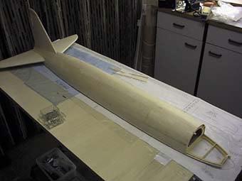
Measure your building board before you start!
Servos and Linkages
As drawn, the DC-3 uses nine servos in all: six standard ones (ailerons[2], flaps[2], elevator and rudder/tailwheel) and three micro servos (throttles[2], plus air valve for the retracts). This is one obvious opportunity for weight saving and, after some thought, Hitec HS81 servos were used throughout. I did though use the metal geared version for ailerons, elevator and rudder. These so far have proven to be up to the job, although one metal geared example does suffer from poor centring. Fortunately it is on the rudder/tailwheel and causes no problem.
I very much liked the snake cum pushrod arrangements supplied for the rudder and elevator. These use quite slender piano wire, onto which short (1cm) sections of the snake inner are fitted at roughly 12" intervals (choose your own preferred units!). This assembly then slides into a light, thin-walled outer, giving you a wire pushrod, supported every foot or so. Low weight, low friction, no slop - very impressive.
When I showed this to clubmate Clive, he rubbed his chin for a moment and then asked why I hadn't mounted the servos under the tailplane and dispensed with 2x 60cm of linkage entirely! He was right of course, so I then spent several evenings working out how best to fit the servos in the tail and adapt the tailwheel and rudder linkages.
The DC-3 has split trailing edge flaps, in three sections. They are a real fiddle to make, but look great when you finally get them working properly. Having now landed the model both with and without flaps, I can confirm they are well worth the trouble.
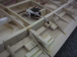
Internal operation of split flaps
The flaps are bottom hinged and I was somewhat surprised to see them operated by external pushrods under the wing, necessitating long, dangly horns. Since the HS81 and its servo horn fit easily within the depth of the wing, I opted instead to fit internal horns to the flaps, so the whole linkage is invisible. The only problem with this arrangement was in working out a way of assembling it all - the three sections of flap have to be slid together on their joiner rods and tubes, then offered up to their hinges as one piece. At some point in this process, the flap horns have to be engaged with the L-bends in the end of the pushrods. Several more evenings of fiddling and fettling can be attributed to this departure from the book, but this time I couldn't blame anyone but myself.
Plastic bits
The kit includes plastic mouldings for the engine cowls, rear tailcone, the cabin and the gigantic wing fairings. I was showing these to clubmate Mick, commenting on their high quality. Now, it seems Mick has been taking lessons from Clive on more than just flying - as soon as he rubbed his chin, I knew I was in trouble. If you need any spare mouldings for a 1/14 DC-3, I'm your man! Well, at least I was allowed to use the cowls.
If you are going to paint your DC-3, there is no reason not to use the mouldings provided (but do check that the full size aircraft you are modelling actually had the tailcone fitted. I discovered that many military examples, including 'mine', didn't.) However, for reasons of weight and personal preference, I had decided to cover my 'Dak' in Profilm and, particularly in the case of the cabin and the wing fairings, I didn't fancy my chances of getting a good match with the painted plastic parts. I reckon that this particular decision added another fortnight onto the building programme but, again, I don't regret it. And yes, the cowls are painted and, no, they don't match the Profilm!
Cockpit and Windows
The instructions recommend you simulate the cabin windows by simply sticking on patches of black trim film, although they do give you the option of cutting out 'real' windows if you wish. I built my wooden cabin with open windows then realised that this gave a beautiful view of bare balsa and I had neither the information nor the inclination to do a fully fitted out cockpit interior. The answer to this dilemma came somewhat surprisingly from my wife's hobby - patchwork. There is a material called template plastic which can best be described as the plastic equivalent of tinted glass. In truth, it is closer to frosted glass, having a rough finish on one side which diffuses the light just enough to let you think you can see through it, but without being able to make out any detail - perfect!
There are of course lots more windows on the DC-3 but I am afraid these got the black trim treatment. The overall effect though is not bad.
The Real Thing
Although there are many full size examples to choose from, when it comes to colour schemes, most of them fall into one of two categories, either military camouflage or civil examples in bare aluminium with a coloured stripe of some sort down the side and a logo on the fin. I needed a colour scheme that was suitable for a Profilm finish, which ruled out the camouflaged specimens and I really wasn't keen on the aluminium look.
Then I came across a couple of pictures of the Portpatrick Princess, operated by the Royal Aircraft Establishment, painted in the well known 'raspberry ripple' colours. I made a few enquiries and learned that the aircraft is in fact still flying but is now with the Battle of Britain Memorial Flight and no longer sports the red white and blue colours. However, a call to the Defence Evaluation and Research Agency at Farnborough led to an invitation to peruse some photos from their archives and I was able to order copies of enough of these to create a reasonably faithful model.
Maiden Fright
If you decided, as I often do, to read this bit first, you may have been surprised not to find it at the end. Well, I reached the point in late June where the model, although far from finished, was basically covered and, once I could balance it and work out where and how to fit the battery, there was nothing in what remained to be done that would increase its chances of a successful first flight. I reckoned that I would enjoy the finishing and detailing a whole lot more if I knew for sure that it was all going to be worth it, so the flying programme was brought forward.
Unfortunately the two 16 turn motors out of the Dave Chinery TG40 unit didn't quite live up to their early promise. One of them in particular substantially under-performed the other and spewed carbon out of the back! I took them both to be serviced and, although they both now perform similarly, they haven't quite come up to my original expectations (I may have over advanced the timing in my earlier tests, giving a somewhat optimistic impression).
As well as being a bit down on power, the model also turned out a bit heavier than I had hoped, at around 9lb 8oz. This was though still within the 8-10lb range recommended for the i.c. version, so it should fly okay - if there is enough power!
With flaps and air retracts, this is by far the most complicated model I have operated, so I took the precaution of writing out a couple of checklists; one to make sure I didn't leave anything at home (such as the pump for the retracts) and a pre-flight sequence, so that I didn't get the model all assembled only to discover that an important lead was still buried deep inside the wing.
Call me paranoid if you like, but I also worked out a flight plan. The main objective of the flight would be to test the model's behaviour when the flaps were deployed, so that I could decide whether to use them for the landing. I also needed a take off circuit that didn't depend on clearing any trees!
A fast taxi run indicated that the DC-3 should be airborne just after the halfway point of the runway, which was reassuring, so the battery was topped up and the Dak was lined up ready to go.
This time, my rudder thumb seemed a bit more nervous and the model weaved somewhat as it accelerated down the runway. As a result, the fence was looming by the time it lifted off, so there was no opportunity to skim along the strip letting the speed build up before starting to climb out. Once over the fence, I started a gentle right turn over the cornfield, but the model really needed more speed and we were still only about six feet above the corn!
Halfway round that turn, and still struggling to gain height or speed, it became clear that the turn was not tight enough to clear the pit area. Not daring to bank any more steeply, I instead turned the other way and started a gentle 270 degree left turn, now flying at around ten feet altitude - and a long way away. Halfway round this turn and with another five feet of altitude gained, a brain cell or two somehow managed to disengage themselves from the task of stopping the model from falling out of the sky and put up a flag to their colleagues, saying 'gear!' I flicked the switch, up came the wheels and suddenly, maintaining speed was no longer a problem and a steady climb was at last established.
After a few circuits, and the injection of a fair bit of up trim, the model was quite comfortable to fly, so it was time to test the flaps. Unfortunately this resulted in serious ballooning and the unscheduled exploration of the tip stall behaviour. This took the form of a 180degree stall turn. Fortunately there was more than enough height to recover from the ensuing steep dive.
Returning to the flight plan, a flapless landing was called and, although the elevator seemed to lack authority on the flair out, the touchdown was smooth, if a little fast and the model rolled down the strip to a halt. After a few deep breaths, I really enjoyed the taxiing back - even if my knees were shaking somewhat.
Several lessons were learned from this short first flight. Adjusting the elevator trim and the flap/elevator mixing were no problem but, after replaying that frightening first circuit in my head several times over the next few days, I had to accept that the addition of a couple more cells would make it a much safer aeroplane.
This was an unwelcome conclusion. First off it meant that the model would now get even heavier. In fact, when finished and equipped with 18 cells, it came out just on 10lbs. Second, whichever way I looked at my assortment of 7-cell and 8-cell packs, there was no sensible way to make up an 18-cell pack, so three 6-cell 2400packs were purchased at great expense. Thirdly, three 6-cell packs don't fit where two 8-cell packs went! In fact the battery stowage arrangement was totally re-worked, the good news being that the new arrangement is actually much better.
The static tests on 18 cells threw up a few teething troubles - a badly soldered brush braid on one motor and a chip falling out of the speed controller! Once these were sorted the rpm and current draw looked good, so off we went for flight no.2. By now the cowls were fitted and some of the markings were in place so the model was beginning to look more like the real thing.
Flight 2
This time the wind direction meant that the climb out circuit had to be to the right, and had to clear the trees. I was glad I had gone for those extra cells! Sure enough, the take off was brisk and the climb out secure, although I had to hold down elevator in to moderate the climb. Unfortunately, deploying the flaps still resulted in a strong nose up pitching movement, which meant another flapless landing. This one was rather bouncy, which simultaneously tested the robustness of the retracts and the deliberate weak link in the battery retention system. After taxiing back with the belly hatch drooping somewhat, an inspection revealed no damage other than the breakage of the balsa sticks used to peg the battery in place.
Flights 3,4 & 5
Having had my fill of flapless landings, I was determined this time to get the flap/elevator mixing sorted. The Multiplex Profi transmitter features a 'Digi adjuster' which enables any selected aspect of the Tx programming to be adjusted in flight. Using this, I was able to ease in just a little bit of flap and use the digi adjuster to re-trim the elevator. To my delight, when I then fed in more flap, no further adjustment was needed.
Flight 3 ended with a smooth landing using half flap, Flight 4 was a repeat performance, this time using full flap. With the flaps deployed, there is no difficulty in extending the flair and quite a bit of speed can be bled off before touchdown. Just as well really, because on flight no. 5 I caught the grass at the side of the strip just after touchdown which sent the model hopping sideways down the runway on one wheel. The retracts survived that too - they are clearly stronger than they look!
The model is now a joy to fly and I am now fine tuning it with a bit of throttle/elevator coupling to overcome the tendency to put its nose up a bit on take off (probably due to my reducing the recommended downthrust a bit too much). The gear and flaps can now be operated without the need for elevator input from the pilot and the main flight controls are smooth and progressive. Power is now more than adequate as inadvertently demonstrated when I had to abort a fully flapped landing approach. I am still stretching the flight duration gradually. Discharging the battery after flight indicates that flights of eight or nine minutes should be possible.
Some carbon discharge is evident from the motors, so it remains to be seen what the interval between brush changes will be.
Finishing Touches
Encouraged by the early flight tests, I was able to relax and enjoy the detailing of the model. I always agonise over just how much detail to include, and I still have more to do around the engine nacelles and cowlings. However, the model is now unmistakably the Portpatrick Princess (if only because it says so on the side of the cockpit!) and, for the present, I am enjoying flying it, and hope to take it to at least one of the electric fly-ins before the end of the season.
   
|
|