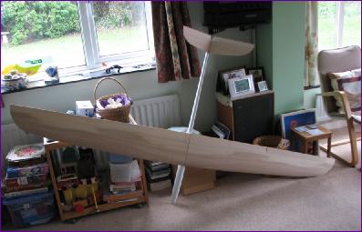
In these days of all-moulded gliders and ARTFs, the Blejzyk range of models could almost be referred to as traditional. They are very reasonably priced (the Hammer cost me just £160 from Flying Dog RC (who have sadly since ceased to be) and the quality of manufacture is very good. The fuselage is a lightweight glass and epoxy moulding with carbon reinforcements in key places and the wings are veneered foam over an aramid interleave. All control surfaces are pre-hinged.
Although designed to take either a classic tail or V-tail arrangement, the default option seems now to be V-tail so, since I don't have any V-tailers in my fleet at present, I just went with the flow. I also got a second outer nose sheath so that I could build the model for slope or flat field electric power.
January / February 2015 The build got off to a rather slow and intermittent start due to it overlapping with the end of the main 2014/15 Winter build (the Duck Twin), so there didn't seem much point in publishing the few pictures taken in January, hence this combined entry.
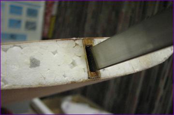
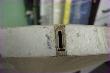
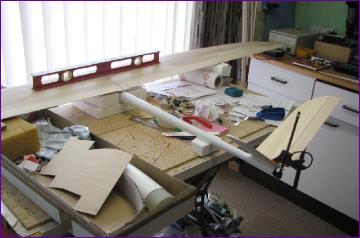
The first job was the wing joner. This consists of a steel blade, which is glued into one wing panel, and a brass box which is glued into the other. These parts locate into wooden boxes built into the spar and are a very loose fit, partly to take up the dihedral in the wing. The recommendation is to fill the void with epoxy but I opted to shim the bar and box with ply to take up most of the slack and reduce the amout of epoxy that has to be worked into the joints.
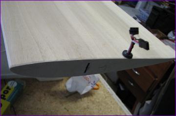
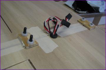
Wooden blocks have to be let into the foam where the wing retaining bolts are going to go. I used Gorilla glue for this job. Before fitting the root ribs it seemed wise to route the servo wires so the next job was to fit the wing and flap servos.
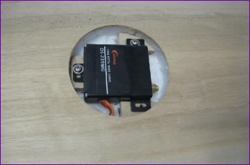
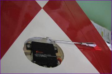
I used Corona DS-239MG servos. These seem to be very good value, fit the pre-cut servo wells perfectly and are metal geared. Hopefully, they will prove reliable too.
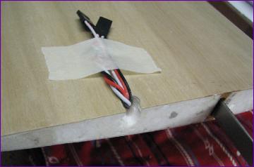
With the wires routed and taped out of the way, the ply wing root facings were fitted and the holes drilled for the fixing blocks. These holes have to be drilled at right angles to the top face of the wing so that the rather neat plastic inserts can be fitted later, allowing the bolt heads to be recessed into the wing. For now though, the holes were drilled just large enough to take the 4mm nylon bolts.
The bolts engage with captive nuts which have to be glued to ply plates inserted into the fuselage. Of course the nuts too have to be installed at an angle to match that of the bolt holes. To make the glueing easier, I sanded the ply plates down to a wedge shaped section to get the angle somewhere near, drilled through the plates then counterbored them slightly to give a nice recess into which to glue the nuts. With the wings taped together, the glue was applied and then the whole lot temporarily bolted together while it set. I used some shorter socket head steel bolts at this stage just to make things easier to manipulate.
The nuts and their plates were then epoxied into the fuselage with the wing again temporarily bolted in place (another stressful job, hoping that everything is lined up and that the glue won't go anywhere it shouldn't!)
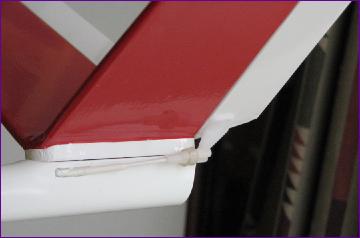
Next, it was time to join the tail halves and repeat the bolt hole / captive nut process. There is a shaped tail seat provided to help join the two halves at the right angle and to seat them onto the fuselage, but I opted to add another piece of balsa along the top of the joint to give a flat surface into which to recess the heads of the retaining bolts (no plastic inserts provided for these bolts).
With wing and tail fixings sorted out and checked for good alignment, I at last felt that I was getting somewhere.
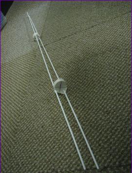
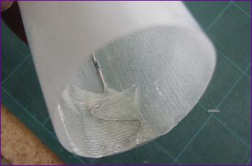
Before turning attention to the nose section, the ruddervator snakes were installed and a plate fitted to take the servos.
I couldn't think of a way of glueing the snakes to the inside of the fuselage so took the alternative route of shaping a couple of pieces of balsa to the fuselage cross section, glueing them to the snakes at appropriate positions, daubing them with glue and pushing the whole lot into the fus. Even this took a bit of forward planning, using the snake inners to guide the outers through the exit holes at the rear.
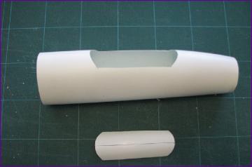
The instructions suggest that an electric motor can be mounted in a second sheath nose which can be interchanged with the glider nose. This means that a lot of the inner nose has to be cut away and I couldn't work out how things would fit together when the nose sheaths were changed. So I opted instead to fit the motor permanently to the inner nose so that to change to glider mode, only the prop and spinner would be removed and the glider nose sheath fitted.
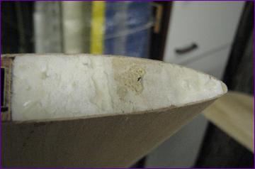
The nose job started with some butchery of the inner nose and the electric sheath.
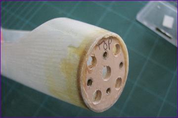
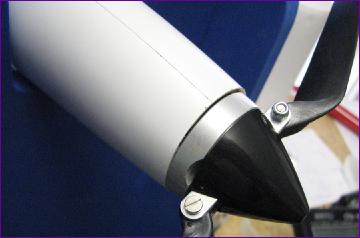
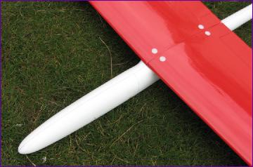
The motor mounting bulkhead was then fitted to the inner nose. Because the fuselage beocmes progressively more ovoid the further back you go, I put the motor as far forward as possible to minimise the inevitable misalignment between the spinner and the fuselage profile. This may not have been a good idea - with a 2200mah 3s LiPo pack pushed back hard against the tail servos, the model is going to need about 2oz of lead in the tail to balance. If this compromises the flight characteristics, I might have to look for a lighter motor.
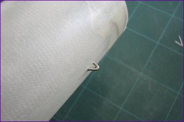
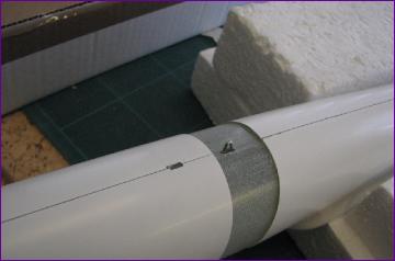
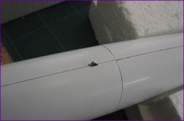
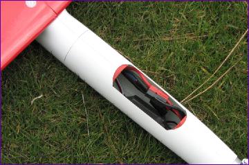
However, the upside of this arrangement is that the integrity of the inner nose isn't compromised and the rather lightweight outer sheath carries no real loads so can be retained by a simple spring clip arrangement.
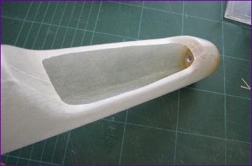
Once the clip was in place, the inner nose could be glued into the rear section of the fus and a corresponding slot cut into the outer sheath.
I had been contemplating leaving the flying surfaces of the Hammer uncovered and just varnishing them to bring out the nice grain patterns. However, my phobia about doing anything involving brushes or paint finally won out and I reached for the trusty covering iron.
There is still quite a bit of work to be done on the wings before they are ready for covering but I decided to make a start with the tailpane and ruddervators so that I could fit the horns and finalise the linkages - I always feel a sense of progress when control surfaces move for the first time under servo power.
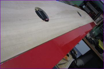
March 2015 This month has been mostly about covering, culminating in the first test flights. The pre-hinged control surfaces on the wings were clearly going to be abit of a challenge so I decided to get them covered first. As is often the case, this job proved to be more formidable in prospect than it was in reality. A strip of covering was pre-cut to size, ironed onto the underside and tucked into the hinge line. Then the wing was turned over and the film ironed down onto the upper surface, pressed firmly into the hinge line while deflecting the surface downwards, then finally ironed into the hinge gap and onto the wing. The end result looks surprisingly neat.
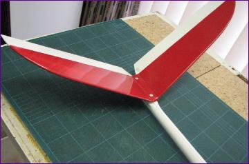
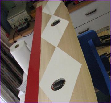
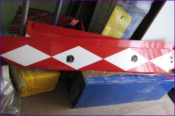
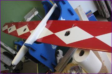
Next, the underside of the wing was covered. I wanted a colour scheme that would show up well and the colours themselves were determined by what film I had in stock. It was only after I had finished the job that I realised that the scheme had probably been subconsciously inspired by my Black Diamond, which I had sold on just the previous week.
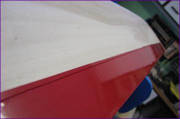
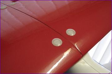
By comparison, the top surface covering was relatively straightforward. Then it was a case of fitting the plastic 'cups' that recess the wing bolts so neatly and then finalising the linkages, servo covers and a few other details.
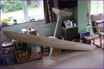
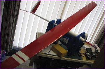
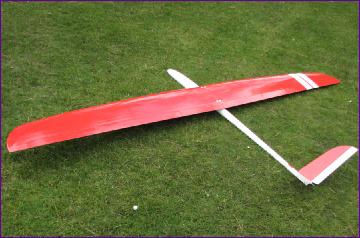
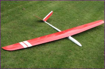
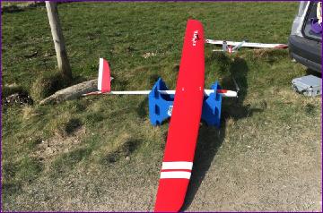
At this point I slipped the slope nose onto the model, bolted the wings on and took it out into the garden to admire my handiwork.
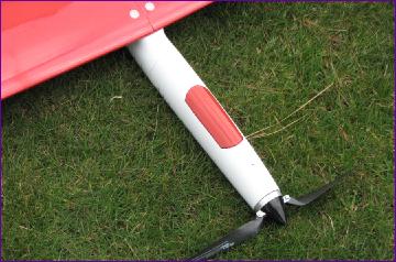
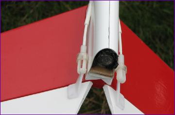
The hatch cut out of the electric nose sheath was painted red in the hope of making the gap around it a bit less conspicuous, and a slug of lead pushed up the tail to bring the cg to the recommended point. The tail weight is anchored by the protruding end of the rearmost tail fixing bolt. The model was placed on a stand and the motor run up on a 13 x 10 Graupner folding prop. This pulled just over 30 amps at 5700rpm which is good enough for first flights. Due to stock shortages at my favoured supplier, a rather over the top 60amp ESC is being used for the moment. With the relatively puny 2200mah 3s LiPo pushed back against the servo tray, the ESC and associated wiring just fits between battery and motor, leaving the connector easily accessible through the hatch.
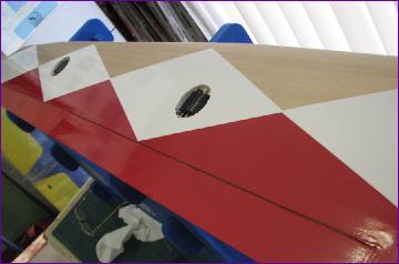
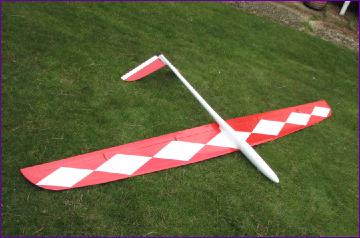
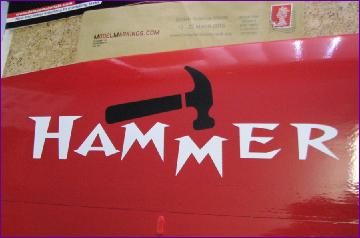
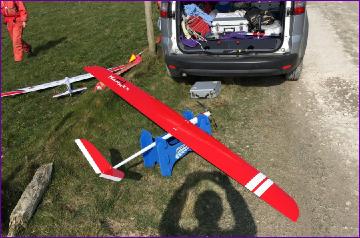
The finishing touch came with a custom piece of artwork provided by clubmate Tim Calvert (aka ModelMarkings.com), then it was off to the slopes, where the challenge of photographing the model with the sun on it but without my shadow in the picture clearly proved too much. Well, I was rather focussed on other things at the time!
The Hammer has had two sessions at the slope in marginal lift and one flying from the flat field, so all have been with the electric nose fitted. So far, I am well pleased with the Hammer's handling. The weight in the tail doesn't seem to be causing any issues and, although the model is by no means twitchy, a dive test (and the fact that it needs very little down elevator to hold inverted) suggests to me that the cg could come forward a touch so I am progressively shaving bits off the tail weight. The power is adequate for a decent 'warmliner' performance off the flat so I have now sourced and fitted a 40a ESC so should be able to shave off a little more tail weight.
At the time of writing I'm still awaiting a good sloping day when I can take the prop off and slip on the glider nose. Maybe then, I might remember to ask someone to take a few flying shots too.
Whilst the Hammer is designated as an F3F machine, I have no racing pretensions and built it as a general aerobatic sloper/ electric warmliner.
Some years ago I built an F3B model and really didn't like it - it was very heavy and, whilst I'm sure it was a competitive racer in strong winds, in the more moderate conditions in which I tend to fly, it didn't suit my more sedate flying style. Phrases like 'balancing a plank on a broom handle' kept coming to mind. I sold it on and it instantly became the buyer's favourite model so I knew the problem was with me rather than the model.
So you will understand that the F3F designation in the Hammer's made me more than a little anxious about whether I had made a good choice. Happily though, I was immediately comfortable with it and look forward tofine tuning the setup over the coming months.
 Before turning attention to the nose section, the ruddervator snakes were installed and a plate fitted to take the servos.
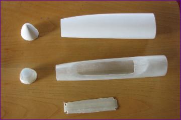

 Whilst the Hammer is designated as an F3F machine, I have no racing pretensions and built it as a general aerobatic sloper/ electric warmliner.