I first spotted Chris Williams's prototype of this model at a scale slope day and then shortly afterwards read about the fun he'd had aerotowing it (you can read more and see a video of Chris's model on the SSUK forum). I've got a bit of a soft spot for vintage gliders but the standard 1/4 scale ones (at about 4m wing span) are a bit ponderous for some of the slopes and landing sites we frequent and can also be rather unweildy to store and transport. However, this one was different. Being built to 1/7 scale, it comes out at just 2m in span.
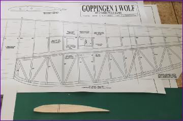
There was just one snag - fearing that I am becoming sensitised to balsa dust, I had resolved not to build anything over the winter of 2018/19 in order to give my airways a bit of a break. Then the Wolf appeared as a free plan in the December edition of RCM&E - temptation! Well, my resolution related to the Winter and, according to the Met Office, Spring begins on the first of March so, towards the end of February, the plans were laid out and a shopping list drawn up. And on March the first, I put in the order for the wood. . .
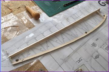
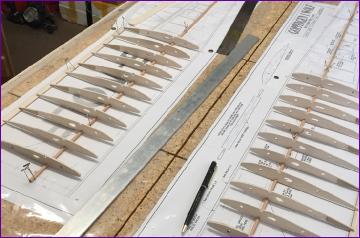
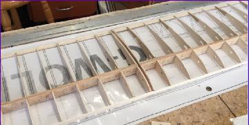
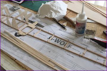
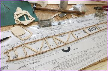
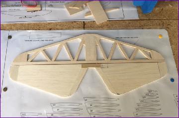
March 2019 The wing build is pretty conventional. The main change I made was to build the wing in two pieces for ease of transport. The plan was cut up and laid out on the board so that the two wings could be built simultaneously, starting with the 3mm square spruce lower spar, the laminated trailing edge and the ribs.
The aileron spar, false leading edge and upper spar come next.
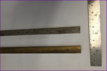
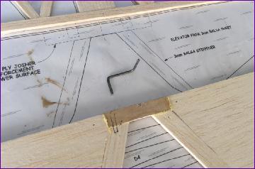
I had initially planned on making a plywood wing joiner. However, it's quite a thin wing and so I felt that something a little more solid might be wise. Eventually I remembered that there were some rusty old steel blade/brass box joiner offcuts lurking in a corner of the workshop and, as luck would have it, the smaller of the two sizes was a perfect fit in between the spars. Sometimes you just get lucky!!
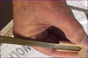
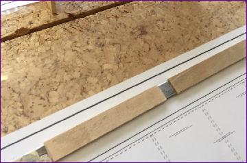
Lengths of the brass box tubing were faced with plywood to bring them up to the width of the spars, then fitted between the spars, secured by ply shear webs front and back.
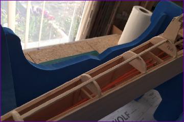
Once the joiners were securely in place, the root ribs were fitted. The plan is to have a ply 'keel' piece projecting out of the wing saddle on the top of the fuselage. This will be slotted and drilled for the joiner blade and a couple of incidence pegs.
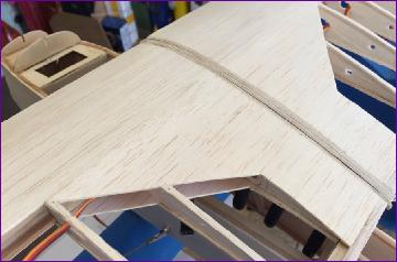
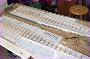
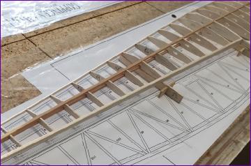
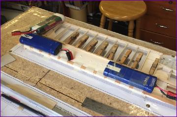
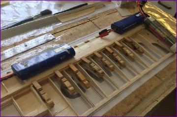
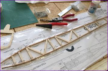
With the framework more or less complete, it was time to do the underside sheeting and cap strips. .
. . . before flipping the wing over, setting it on the jigs, and repeating the procedure on the top.
Of course the above description glosses over all the really time-consuming little preparatory jobs of making sure that the aileron servos will fit, re-profiling any slightly misaligned ribs, sanding back the aileron spars and false leading edges, fitting blocks for the aileron hinges and incidence pegs, etc., etc..
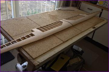
I suppose that, at this point, I should really press on and finished the wings - they still lack wingtips, leading edges, ailerons, root facing ribs, incidence pegs, strut fixing points etc.. However, I fancy a change of scenery so have cleared the bench in readiness to make a start on the fuselage next month.
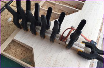
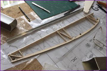
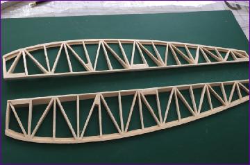
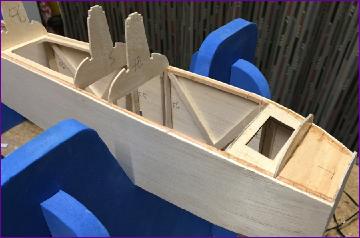
April 2019 Fuselage construction starts with the side frames. The 3mm sq spruce longerons were pre-bent at the front end in the steam from a kettle. The ply formers were trial fitted early on in the proceedings and the uprights alongside them cut to fit.
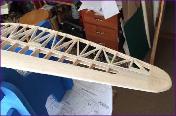
The second side was built over the first (with a sheet of polythine in between), then the sides were glued to 1/16 balsa skins before being joined around the central formers and a ply alignment plate.
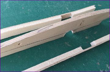
Pulling the fuselage sides in at the nose is always a slightly tricky process. The ply alignment plates are essential here - without them any attempt to pull the nose in would just bow the 1/16in ply formers. Rather than dampen or re-steam the longerons, they were notched with a razor saw to facilitate bending without building up too much stress. Even so, I found it easiest to do the job in two phases as illustrated in the pictures below.
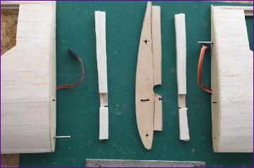
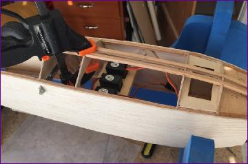
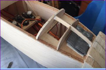
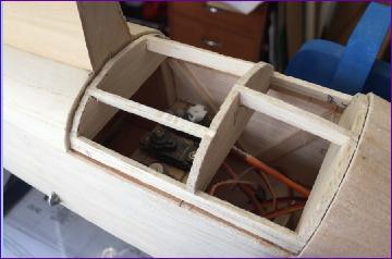
Before doing anything that might impede access, I thought it best to install the servo tray and sort out the rudder and elevator linkages.
Of course, this meant building the tail surfaces. The tailplane is straightforward, being built up from 3mm balsa. The elevators are also 3mm balsa and, by making the joiner from 1.5mm balsa sandwiched between two strips of 1/32in ply, I was able to fit a piece of 16swg piano wire to form the basis for an elevator horn.
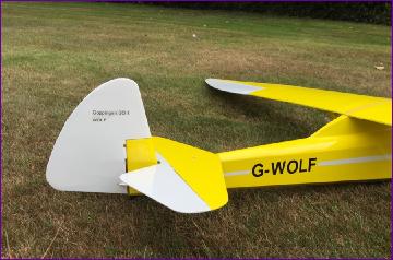
Last job of the month was to build the fin and rudder. All pretty much self-explanatory and as per plan.
There's still work to be done on all the tail surfaces but at least they are at the point where they can be dry fitted in order to finalise the routing of the linkages.
Considering what a poor month it has been for flying opportunities, I had expected to get a bit further with this build than I have. However, there are no deadlines and there have so far been no real problems, so if it takes another month or two, so be it. Anyway, I still haven't given any thought to a colour scheme or where to find a 1/7 scale head and shoulders pilot. . .
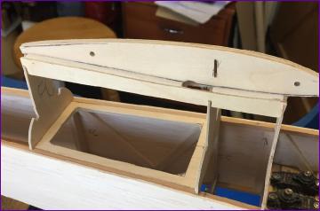
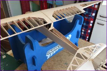
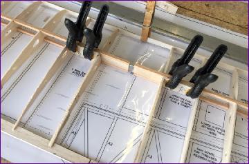
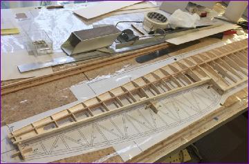
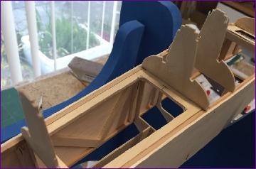
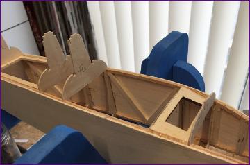
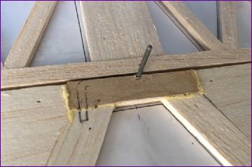
May 2019 First job of the month was to sort out the wing mounting and joining arrangements. The plan shows a one piece wing so, having instead opted for a two piece wing, I was rather on my own here. These first two pictures show the component parts.
The side pieces were glued onto the central 'keel', using the wing as a guide, then the whole assembly glued in between the 1/16in ply supports.
The next two pics show how it all goes together, although they were actually taken earlier during one of the many preliminary dry fits.
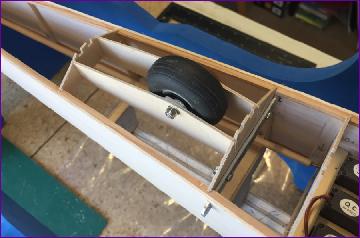
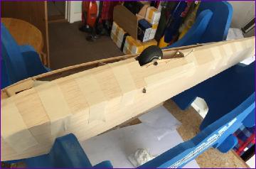
Now that I was reasonably happy about routing all the wires and control linkages, the fuselage was flipped over, the wheel fitted and the bottom sheeted in.
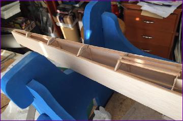
Next up was the upper rear sheeting. The orange tubes you can see in the first picture are guides for the closed loop rudder wires. These aren't strictly necessary but they do make it easier to route the wires later on and also I wanted to ensure that the aileron extension leads couldn't snag the rudder wires when the wing is fitted and removed. Suddenly the fuselage is beginning to take shape.
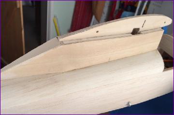
I felt that the final tidying up of the wing pylon should only be done once the leading and trailing edges of the wings had been sanded to shape. But equally, I wanted to fit the leading edges after fitting the wing tips in order to give the latter a bit of support.
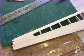
But, to help with sizing and positioning the wing tips, I needed to build the ailerons. There are a lot of parts in these and Chris had warned that, if you get too finnicky, they can take a long time. Where diagonals are involved, I find it quicker to fit straight rib followed by diagonal followed by straight rib etc. This avoids the challenge of trimming diagonals to fit between two ribs simultaneously.
It all went well but I did find I needed to cut the ribs oversize. Whether this is an error on the plans or whether my wing is too thick at the aileron spar, I can't be sure.
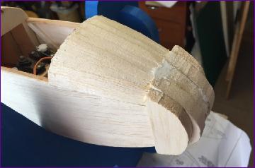
Hinge slots were cut next so that the ailerons could be positioned to aid in building the wing tips. A 1/32in ply lamination was incorporated into the tips for a bit of ding resistance.
Leading edges were then fitted and given their first sanding.
There's not an awful lot left to do now but, before proceeding with the upper nose planking, I assembled the model to get an idea of how much noseweight might be needed. As a result, 2oz of lead has been stuck to the handily located ply plate between f1 and f2.
As the month drew to a close, planking was just beginning. . ..
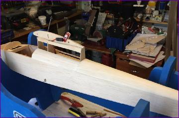
June 2019 When the nose was planked, I was able to take the model outside and make some dust. I'm always surprised at the transformation that a planked section undergoes when attacked by a sanding block.
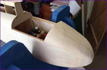
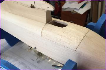
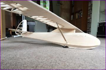
The next job was to sheet in the wing pylon with 1/32in ply before tackling the hatch/cockpit area.
The hatch is shown on the plan as balsa sheeting over a framework. However, since the planking on the nose section went so well, I decided to do the same here, which allowed a slightly smoother transition into the contours of the nose. The cockpit aperture was left slightly undersized for the time being with a view to matching it to the still-to-be appointed pilot.
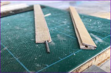
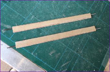
My first attempt at the strut fairiings used 1/32in ply for the side faces. This was a failure, the ply being too stiff to bend into shape around the 2mm threaded wire core. A second attempt using 1/64in ply fared much better. The good and the bad are shown in the first picture below.
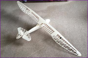
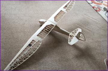
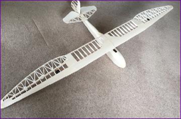
Time to assemble the naked airframe one last time before getting the covering iron out.
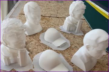
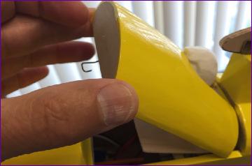
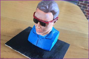
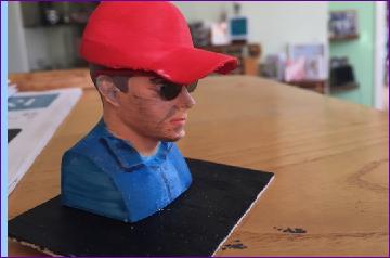
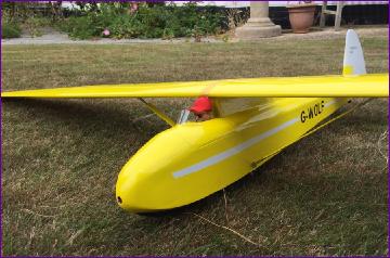
By the time the covering was basically done, I was given a selection of candidate pilots, 3D-printed by clubmate Frank. At the time of writing the selection interviews haven't been completed but, after a few trial fittings I was able to finalise the size of the cockpit aperture and do the last bit of covering.
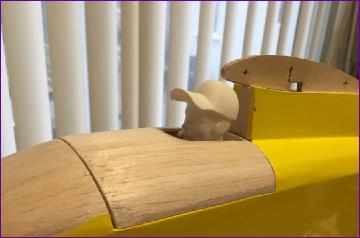
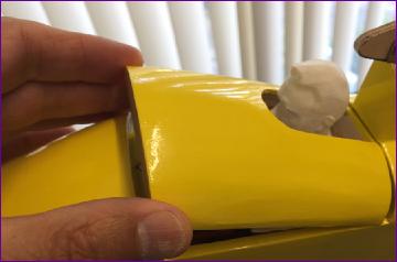
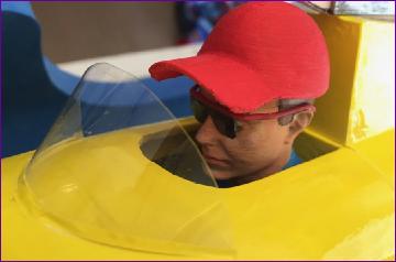
However, if you look at the proximity of the pilot's head to the leading edge of the wing you can see that, even though the hatch lifts from the front, there is a problem. . . . .
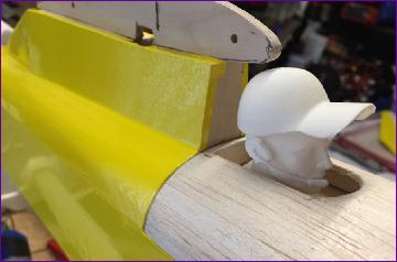
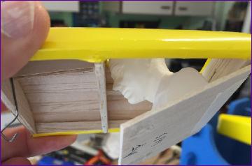
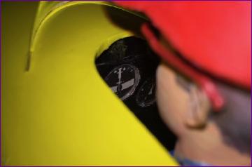
After considering lots of ideas involving foam cushions, springs, rubber bands etc., I finally settled on the solution illustrated in the following picture sequence. The cockpit floor is hinged at the rear and a fixed cross member in the fuselage supports the floor horizontally as the hatch is lowered into position. I've since painted out the cockpit interior and fitted a few instruments. All I need now is to find someone to paint the pilot.
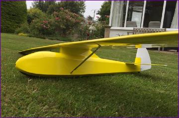
So, the outstanding jobs list is now quite short:- windshield, pilot painting, registration and markings. All up weight at this point, balanced on the front of the spar, is 2lb 3oz; a few ounces less than the prototype. So, fingers crossed, I hope to be able to report on a successful maiden flight next month.
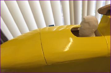
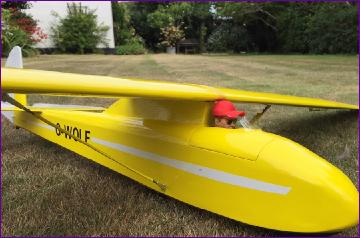
July 2019 Clubmate Mike Roach kindly undertook the job of painting the pilot for me and, on his recommendation, I added the sunglasses. These are simply made from a plastic coated paperclip, with the lenses snipped from an old pair of overspecs.
With a simple windshield fitted, the pilot was re-fitted into the cockpit. The second picture below is about as much as you can see of the instrument panel, but at least I know it is there!
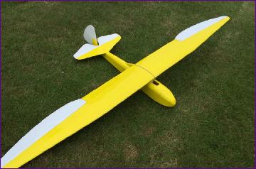
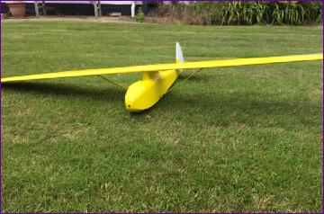
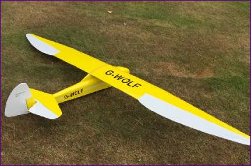
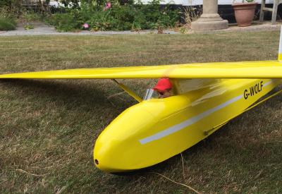
So, with markings applied (thanks Tim), one more photocall on the lawn, then we await the opportunity for a maiden flight. . .
Well, for once, I didn't have too long to wait. Sunday 21st July was a Scale Day at White Sheet RFC. With forecasts of a light to moderate breeze straight into the main bowl, the omens were good. We arrived earlier than usual but still found the hillside packed with models and flyers and struggled to find a suitable parking spot. Then, before the Wolf had even come out of the car, the skies darkened and a steady drizzle set in. In common with most others, I eventually gave up on the morning and settled for an early lunch in the car. Then, just after midday, the rain at last stopped and the unpacking process could be re-started.
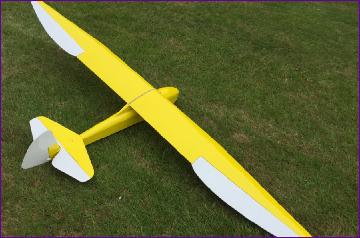
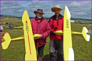
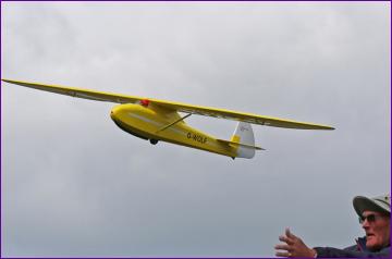
Although the skies were now a lot brighter the wind was also a fair bit stronger and it was clear that it was causing problems for several pilots in judging the landing approach and achieving a smooth arrival. By now, clubmate Alex had appeared and had his Wolf assembled too. Chris Williams photographed the two of us with the models (see below) and if you think you can see a touch of apprehension in our expressions, you'd be right!
With the static pics in the can though, Chris assured us that the models would cope with the wind just fine so we were persuaded to give it a go.
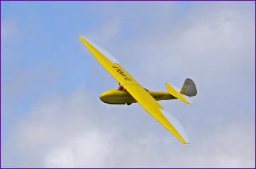
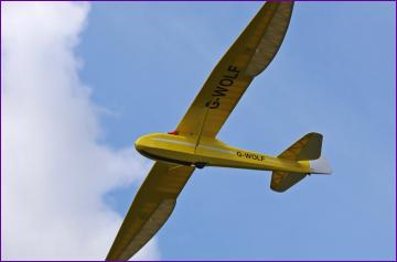
As you can see from the above pictures (also taken by Chris), he was absolutely right. The Wolf was surprisingly at ease in the windy conditions and, once the elevator was trimmed, flew beautifully. Deploying a bit of up 'spoileron' didn't upset the pitch trim so a landing was called. The landing was safe but not very elegant (I blame low level wind shear) so I didn't push my luck any further. Alex also successfully maidened his model and a third Wolf had also been maidened earlier in the day before the rain came. I look forward to many more forays from the slope and will try to report back when the Wolf has had its first aerotow.
Footnote - August 2019 I have now had a couple more flights off the slope in more moderate windspeeds and am very pleased with the Wolf's performance. It can be cruised around in a scale-like fashion but, when bored with that, can be thrown around in a manner more appropriate to an aerobatic model. It has also now had its first couple of towline launches. It goes up the line happily enough (although I did feel the need to hold a bit of up elevator in to maintain tension on the line). However, it's no thermal soarer so, unless strong lift is encountered, flat field flights tend to be short and sweet so I think the Wolf will be seeing more of the hills than the towline in future.
 Once the joiners were securely in place, the root ribs were fitted. The plan is to have a ply 'keel' piece projecting out of the wing saddle on the top of the fuselage. This will be slotted and drilled for the joiner blade and a couple of incidence pegs.
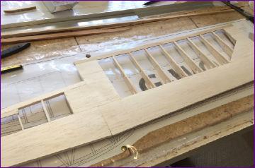
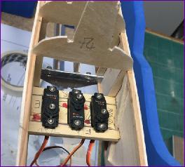 Before doing anything that might impede access, I thought it best to install the servo tray and sort out the rudder and elevator linkages.
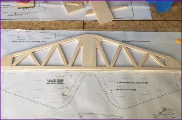
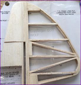 Last job of the month was to build the fin and rudder. All pretty much self-explanatory and as per plan.