Delayed Reaction? I'm not sure exactly when the plastic revolution first hit the R/C glider scene - probably somewhere just before the turn of the millenium I think. To my eyes they were a bit like the supermodels of the slope - elegant in their own way but really just a bit too skinny to be interesting. Watching people fly them, the idea seemed to be to work the lift for a while then, having reached a fair altitude, dive down and zoom through the airpspace where everyone else was flying, hoping that it would make a loud enough whistle to scare everybody out of the way. So, whilst the technology and the performance were undeniably impressive, I didn't feel any real urge to join in with this trend - and the eye-watering prices demanded didn't help.
Fast forward twenty years or so, and I find myself with more electric powered models than I can sensibly fly in a year, an aged fleet of slopers, some of which date back to the 1980s and an increasing sensitivity to balsa dust which is taking much of the pleasure out of traditional building. So, looking arouind for something to refresh the sloping collection involving enough building work to keep me busy for at least a bit of the winter without getting dust up my nose, I at last found myself contemplating the plastic option.
Selection On the face of it, there's no shortage of choice in this sector. There's also a surprisingly wide range of prices. After all these years, I still haven't learned to love the ultra skinny fuselages of the out and out competition 'supermodels', so I found myself leaning towards those with a more semi scale appearance. I was clear that I wanted something that would fit betwen my venerable Alpina Magic and the more recent Blejzyk Hammer - and I definitely wanted to stick to a three figure budget!
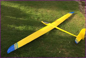
So, having clarified my thoughts a bit, I consulted fellow flyers and received a number of useful recommendations. Unfortunately, following these up, I found that stock levels in the UK were not great, many models only being available to special order. However when I contacted Pete at South Coast Sailplanes about the X-Calibur, and found that he had one in stock, I decided to look no further. The bonus was that, SCS being a local supplier, I was able to go along and have a look at the model, pay the money and bring it home - no delays, no risk of transit damage.
Inspection I'm not sure when the X-Calibur went into production. Certainly there are references to it online dating back to 2006, so it's a well established, well proven design. However, I suspect that some of the jigs, moulds and fixtures used during its manufacture may also be showing their age. A trial assembly of the wings to the fuselage showed that some of the holes for the incidence pegs needed opening up a little and then, when they were sorted, the wings still didn't push fully home. Investigation showed that the joiner was the correct lenght but the holes in the wing just weren't deep enough. I was reluctant to shorten the joiner so some anxious work with 10mm drill was needed to fix the problem. I suppose that I shouldn't have then been surprised to find that the tailplane halves needed similar treatment before they too could be pushed fully home.
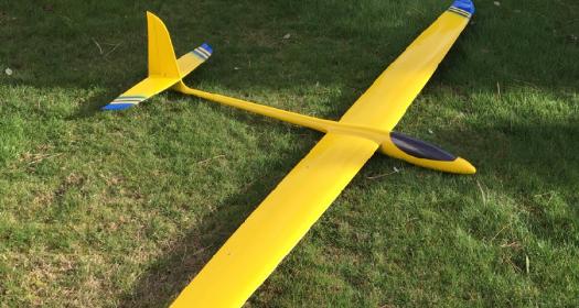
That said, the overall quality of the main parts seemed pretty good to my inexperienced eye, although the paint layer on the upper surface of the wings is a bit thin and streaky. The fittings supplied are of good quality, but exactly what is and is not supplied seems a little random. For example 2mm closed loop fittings are supplied but no wire or ferrules are included. No servo tray or fin post is provided but happily wing servo covers are - although mine were the wrong colour and had to be replaced.
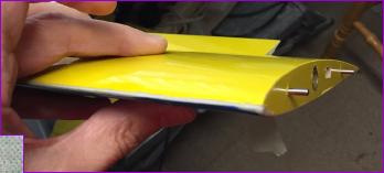
I was a bit surprised to see that the top and bottom colours of the wing didn't meet on the leading edge, leaving a white line (see photo). However, I'm told this is quite common with the manufacturing methods employed. Certainly the leading edge profile feels perfectly smooth so it's only a cosmetic blemish.
When researching this model, one online reviewer raved about the excellent quality of the English instructions, so I was a bit taken aback to find that the link on SCS's website took me to an Italian version. Having failed to find the English version online, I e-mailed Pete at SCS asking for a pointer but got no response. I did though find English instructions for some of the more recent models in the X-models range, in particular the Sword so, with the aid of these and some Google translations of selected bits of the Italian, I was able to muddle through. Some bits of the Google translation were though more entertaining than helpful. For example, I was perplexed (and slightly perturbed) by "insert a "CERD" hinge in the first cut and continue inserting the "PTDR" pin in - thus castrating the zip"!
Tail This model has an all-moving tailplane so one of the first jobs is to fit the tailplane operating crank and elevator pushrod. The crank is built up from three layers of carbon fibre, and is connected to a carbon tube pushrod via a 3mm clevis and threaded rod, embedded in a hardwood dowel. As always with all-moving tails, installing the pivot tube is a critical operation to avoid a wonky setup. To their credit, X-Models acknowledge that the holes in the two fuselage sides may not quite line up and so they are drilled undersize and the instructions spell out in some detail how these holes need to be opened up carefully to optain the correct alignment.
I managed to avoid the trap of setting up the tailplane at right angles to the fin and instead temporarily fitted the wings and lined it up with them. There is a slight twist in the fuselage so the fin isn't quite upright but this is far less noticeable than a cockeyed tailplane.
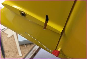
The rudder is closed loop operated and, peering down the fuselage from the rear end, it's clear that the location of the exit holes for the closed loop wires is pretty critical: too low and the wires will be trying to saw their way through the elevator pushort, too high and they will rub on the inside of the fuselage at the base of the fin. Obviously all this has to be sorted out before you fit the fin post and seal it all away for good.
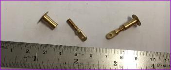
The rudder horn itself is a length of 3mm studding and two nylon tabs. I used a bit of yellow heat shrink sleeving to hide the exposed threaded section.
Fuselage - part 1
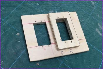
You are left to choose how far forward to fit the servos. This is fair enough because, with that spacious cockpit area and rounded nose, many builders might choose to fit an electric motor to this model. I admit that I was sorely tempted but eventually persuaded myself that this isn't a model I'd want to fly from the flat and, if a motor is required on a slope day, I'll fly something else. So, after a few measurements and a fiddle around with a cardboard template, I cut out a servo tray from 1/8in ply. Bearing in mind the earlier thought about getting the closed loop wires to clear the elevator pushrod, I jacked up the rudder servo with a 1/4in ply doubler.
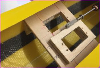
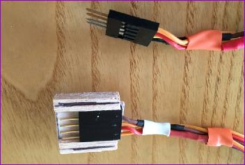
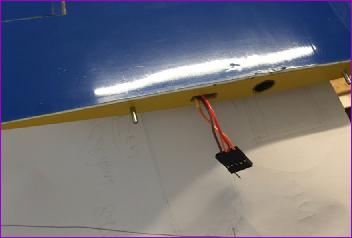
Before gluing the tray in though, I was keen to sort out the wiring harnesses to the wing roots. Green Multiplex connectors are provided and, whilst I have used these successfully on other models to make automatic connections when the wing is installed, for this model the recommendation is to fix one half of the connector and leave the other half free. Since the wings simply push home and are secured with tape, this recommendation to have one half of the connector floating seems very sensible. The only trouble is, these connectors are not easy to separate when one half is buried in the structure so I opted instead to use multiway connector housings which take the inserts from standard servo and extension leads. The downside of these is that the half with the pins does not come with a protective shield so I built a housing out of ply and balsa, ready for gluing into the fuselage side.
Wings
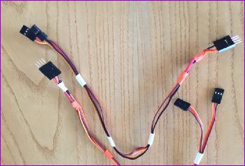
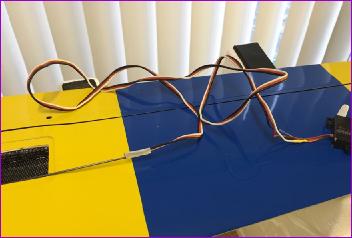
Whilst the above harnesses were simply made from pairs of extension leads, the wiring for the wings inevitably involved a bit more customising and soldering. One benefit of the hollow moulded wing construction though is that threading the wires through was a doddle!
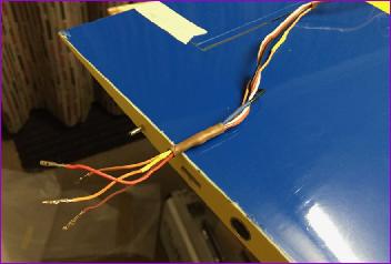
With everything threaded through, the inserts from the servo plugs could be popped into the multiway housings to complete the job. A polarising pin was fitted to the spare slot in the connector. This was later cut off flush with the housing.
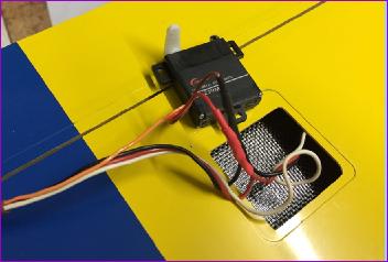
Finally, the servos could be installed and linked with the control surfaces using the supplied horns, pushrods and clevises. As always, I had to supply my own locknuts!
The clevis pins were a slightly loose fit in the brass horns so the holes were coated with cyano and then gently reamed out to achieve a better fit.
Fuselage - part 2
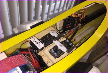
Once the wing servos had been checked out through the harnesses, the fuselage wiring was installed, followed by the receiver and servos, not forgetting a couple of tubes to route the aerials to suitable locations. There is some carbon in this fuselage but I'm hopeful that, with careful siting, internal antennas will work okay.
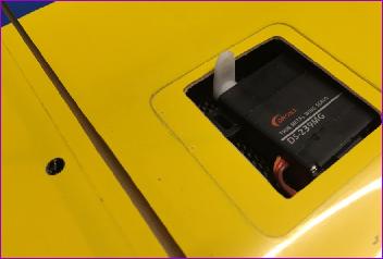
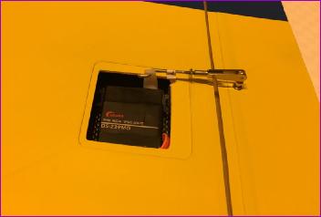
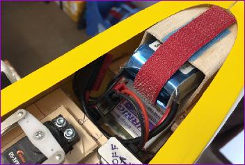
Some years ago, I ditched NiMH receiver packs in favour of using LiPo batteries with regulators. This is partly out of miserliness - I have a steady supply of LiPo batteries which, whilst getting a bit tired to use in electric models, are still more than capable of driving a receiver and servos. What's more, if a model hasn't been flown for six months, I can pull it off the rack and be pretty confident that there will be plenty of charge left in it. Anyway, a 3s x 2200mah battery was earmarked for the X-Calibur and I made up a ply and balsa box for it to slide into. All of a sudden that spacious fuselage was looking rather full!
A mount was made for the regulator to sit below the battery and all that remained now was to work out how much lead was needed to balance this model - and where it would go.
A quick balance check showed that a substantial amount of lead was going to be required. First of all some 12oz of lead shot was fited into the nose, retained by a balsa bulkhead. That word 'retained' actually hides a bit of a trauma. I stirred some silicone adhesive into the lead shot and then secured the bulkhead with more silicone. Then a piece of polythene was wrapped around the front of the battery box which was temporarily inserted and the model stood on its nose overnight for the silicone to set. In the morning all seemed well so the battery box came out and I started to think about how best to stow some more lead underneath it. When I looked in the fuselage some minutes later, I was horrified to find that the dam had burst, so to speak, and a slurry of silicone and lead shot was slowly making its way along the fuselage floor!
Stuffing it all back in place was, as you can imagine, a messy business. The model was again stood on its nose for a further two days and since then all has been well. A polybag containing a further 7oz of lead shot was squeezed in under the battery box (to be replaced with solid lead once I'm sure how much is needed. This brought the cg to the rearward limit of the recommended range so the last step was to tape a couple of strips of lead to the battery itself to bring the balance point to the front of the range for the maiden flight.
At the time of writing, the X-Calibur has been ready to fly for a couple of weeks but there is still no sign of a suitable weather window to fly it. It is January, and I really would prefer to do the maiden flight without worrying whether I am about to lose all feeling in my fingers or suffer from watering eyes or fogged up goggles, so I'll have to be patient for a little while yet.
I'll report back after it has had a few flights.
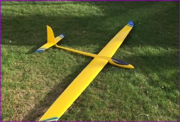
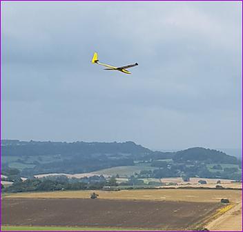
December 2022 Well, it's taken a while, but I've just noticed the above promise to report back on flying the X-Calibur. In short, it does everything I expected and hoped for.
This is my first all-moulded model so I can't say how it compares to other similar offerings but, for me, it is an excellent heavyweight aerobatic model - a complete contrast, for instance, with the Phase 6!
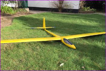
I have some aileron to flap coupling for aerobatic mode and, when you enter a roll at speed, there's a very satisfying whistle from the ailerons.
It responds well to crow braking so, in spite of its speed and weight, can cope pretty well with restricted landing areas.
 English version online, I e-mailed Pete at SCS asking for a pointer but got no response. I did though find English instructions for some of the more recent models in the X-models range, in particular the Sword so, with the aid of these and some Google translations of selected bits of the Italian, I was able to muddle through. Some bits of the Google translation were though more entertaining than helpful. For example, I was perplexed (and slightly perturbed) by "insert a "CERD" hinge in the first cut and continue inserting the "PTDR" pin in - thus castrating the zip"!
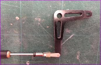 This model has an all-moving tailplane so one of the first jobs is to fit the tailplane operating crank and elevator pushrod. The crank is built up from three layers of carbon fibre, and is connected to a carbon tube pushrod via a 3mm clevis and threaded rod, embedded in a hardwood dowel. As always with all-moving tails, installing the pivot tube is a critical operation to avoid a wonky setup. To their credit, X-Models acknowledge that the holes in the two fuselage sides may not quite line up and so they are drilled undersize and the instructions spell out in some detail how these holes need to be opened up carefully to optain the correct alignment.