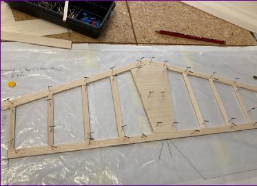
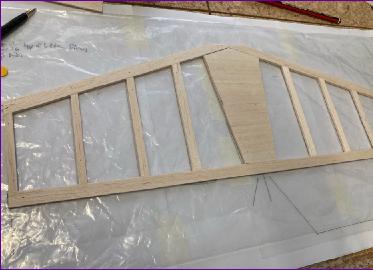
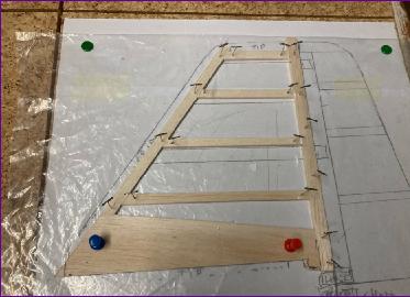
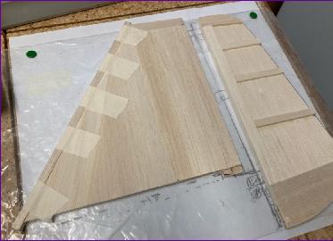
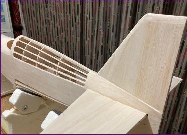
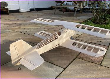
November 2020 (click here to return to Part 1) The tail surfaces are shown on the plan as solid 1/4in balsa. I always prefer to build a simple framework and sheet top and bottom with 1/16in balsa. It may not save much weight but the resulting item is stronger and stiffer and, by using harder wood for the tips and leading edge, more ding-resistant.
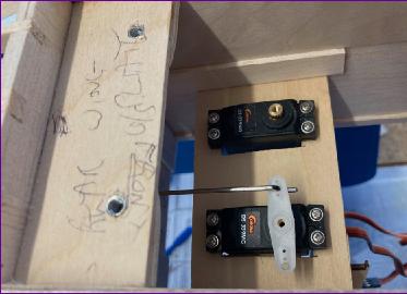
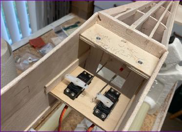
The elevators were built similarly, but inside out - a 1/16in balsa core with 3/32in balsa framework top and bottom. This arrangement makes sanding a tapering profile into the elevators very easy. Rudder and elevator servos were mounted at the rear of the wing seat and the elevator linked by a steel pushrod in a nylon guide tube.
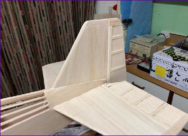
The fin and rudder were tackled in a similar fashion, this time using a conventional nylon snake for linking to the servo.
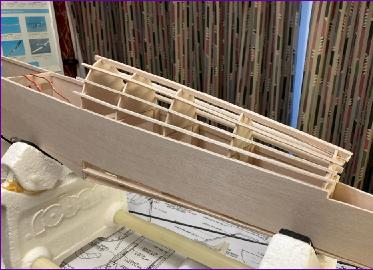
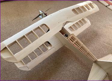
The rear turtle deck came next. Because I'd left off the tops of the formers to enable the basic fuselage to be constructed upside down, I was able to dry fit the formers, mark the stringer positions then remove them in order to cut the notches. This worked out pretty well - much easier than cutting the notches in situ.
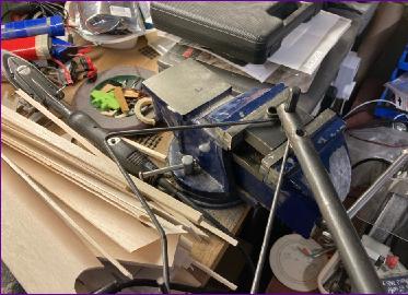
Then it really was time for the dreaded cabane wires! I was lucky enough to be given a K&S Mighty Wire Bender many years ago. It doesn't see the light of day very often (except to be loaned out to fellow modellers!) but at times like this it really comes into its own. The first pic below shows it in use. Sorry about the background clutter, but that is the reality of working in my over-full workshop cum model storage room.
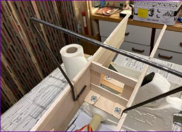
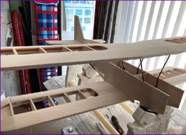
with notches cut in the upper longerons to locate the wires fore and aft, I found that there was just enough 'twang factor' to support the weight of the upper wing by friction alone. So, with the lower wing and tail surfaces temporarily fitted to help with alignment, after a few careful measurements, the position of the wires was marked on the inside of the fuselage sides.
Balsa blocks were then glued to the fuselage sides to positively locate the wires. However, the wires themselves were not glued in at this stage.
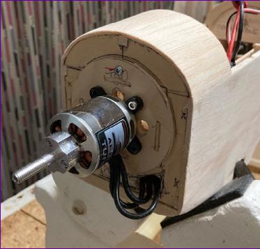
Now, with the motor temporarily held in vaguely the right place, the balance of the model could be assessed for the first time.
As far as I could judge, everything looked promising so there was no need to exend or shorten the nose. However, I've been caught out before by balance points shifting inexplicably during the latter stages of construction and finishing so wanted to have as much leeway as possible in battery positioning - all the more so since ideally I'd like the option of using 3300mah or 5000mah batteries.
As it happened, over the Summer I'd been following a beta build of the Warbirds Replicas Mustang and had put my name down for one. By coincidence, the kit arrived just as I approached this point in the Aeromaster build. Whilst I don't intend to start the Mustang until next year, I couldn't resist opening the box and having a look at it. Of course, I took particular interest in the motor and battery mounting arrangements!
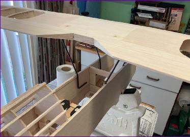
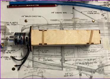
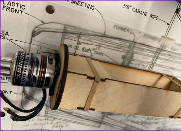
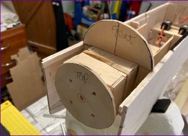
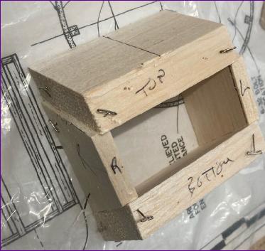
These two pics show the dry-assembled battery box for the Mustang positioned over the Aeromaster plan.
I believe that this concept originally arose when contemplating how to make a model easily adaptable between i.c. and electric power. The idea is that, by threading the battery box through the original firewall, the difference in length between various electric motors can be accounted for, so that the firewall and cowl do not need to be modified.
In my case, I'm free to put the firewall where I want and was planning to shape the nose rather differently from the original anyway so arguably didn't need this flexibility. However, it still struck me as a neat arrangement and would keep open the option for a last minute 'Pinnochio' operation should the cg need to be brought forward. So, I shamelessly copied the idea, making the box a little deeper to keep open the option of using the larger 5000mah 4s batteries.
After another assembly and balance exercise, I felt confident enough to finalise the position of the firewall. The fuselage sides were then trimmed back and it was time to start making up the cowl.
This was the usual exercise in 3D visualisation, hoping that, when it is all sanded back, you don't end up sanding fresh air!
The cowl locates on four small dowels (cocktail sticks). At the moment I haven't decided on a retaining method - it's a pretty snug fit so it may be that just a strip of covering over the joint will suffice.
From here, it was now just a question of working my way back along the top of the fuselage. For some reason, I seem to have forgotten all about taking photos at this point. However this upper decking was simply formed by rolling 3/32in balsa sheet over a few formers. By extending the battery hatch back to the rear cabane wire position I have been able to defer the final fitting of the wires until after covering, which hopefully should make things a bit easier.
The last little job on the underside of the fuselage was to make a filler piece to go over (under?) the undercarriage. This u/c is an off-the-shelf item so had to be recessed quite deeply into the fuselage to avoid giving the model too much of a 'sit up and beg' attitude on the ground.
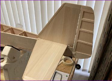
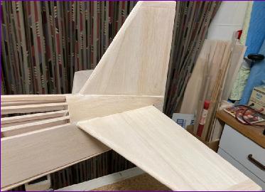
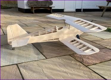
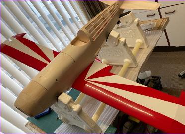
The tail surfaces were then finally fitted, and the fin to tailplane fairings made out of 1/16in balsa. Although these fitted pretty well, they did need a smear of filler to blend in smoothly so this seemed as good an opportunity as any to go over the whole framework, filling the odd dings and dents accumulated along the way.
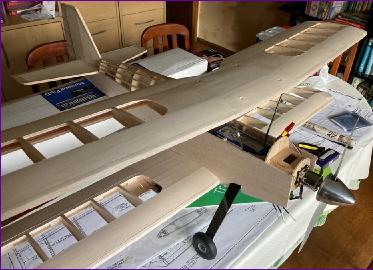
The wings were then taken outside for the leading edges to be finally shaped, then everything was giving a final sanding before being coated with Deluxe Materials Eze-Kote. This is like an odour-free sanding sealer and hardens off the balsa, giving a good surface for covering.
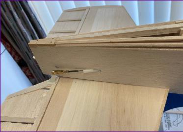
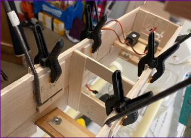
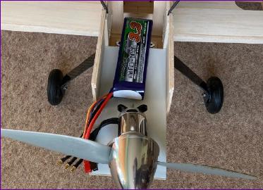
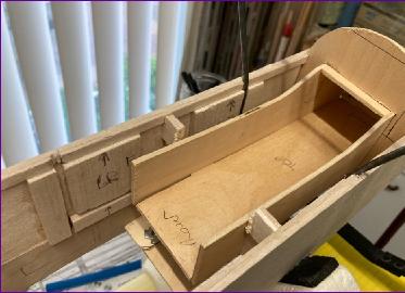
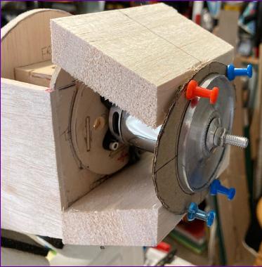
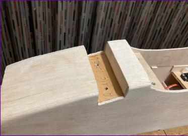
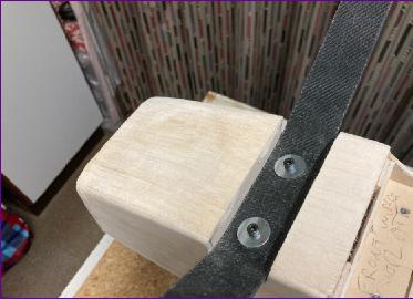
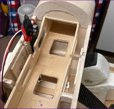
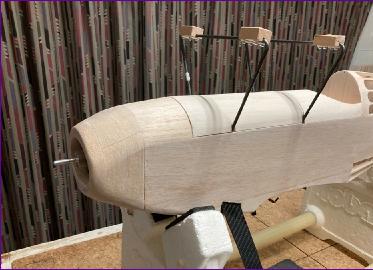
The remaining photos were taken as the component parts of the model were re-assembled one last time before moving on to covering. The first two pictures show how the battery box fits. It is secured by two screws into the firewall (the top one visible in the first picture), and a third screw through the floor of the battery box, towards the rear, seen in the second picture. This means that, when I finally come to glue in the cabane wires, the battery box can be slid out again to improve access.
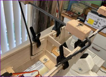
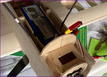
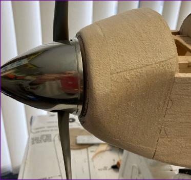
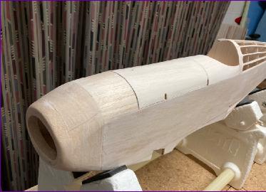
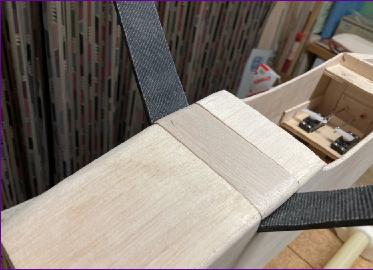
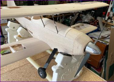
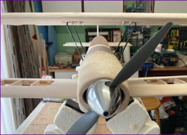
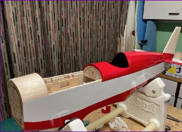
The next sequence of three pictures shows the cabane arrangement, hatch and nose shape.
The hatch has a spring clip to retain it at the rear and will have a sliding bolt canopy latch fitted at the front after covering.
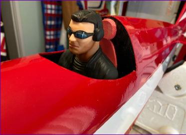
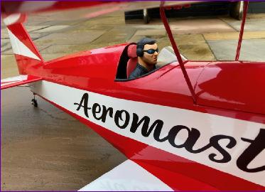
The front aperture in the cowl has been widened to admit some cooling air which exits through a large hole in the cockpit floor. I do intend to add a windscreen after covering and will keep a look out for a suitable pilot.
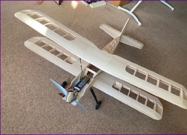
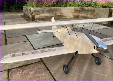
So that's where we got to on the last day of November. However it was too dark by then to get any outdoor photos so, if you'll forgive a slight bending of the timeline, these last three photos were taken today (1st December).
I'm somewhat surprised by how quickly this model has come together. However there is no doubt that the run of rubbish flying weather in October, followed by the four week lockdown in England in November has had an impact.
Still, this is a neat point to round off this marathon diary instalment - and the lock down ends tonight so I'm going flying tomorrow!!
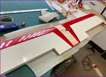
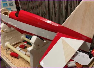
December 2020 I tend not to take many photos during the covering stage on the basis that they aren't particularly informative. However, a start was made by covering the rear portion of the lower wing in white oracover, followed by the red on the leading edge and centre section. I was a bit concerned that I might run out of red film so left the portion that will be inside the fuselage uncovered.
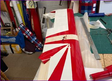
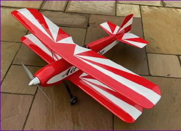
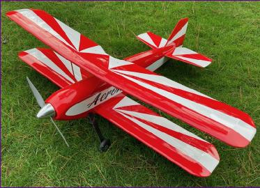
I'd decided to go for a sunburst scheme so now I was faced with the challenge of how to apply the rest of the red 'rays' on top of the white film without suffering from too many trapped air bubbles.
It would be possible to cut the rays out of red vinyl, then they could be floated on over a film of soapy water, allowing the air to be squeegeed out. However, I didn't fancy that for two reasons: Firstly the red vinyl I have is not a precise match for the red film. Secondly, the rays have to go over the wing tip and I didn't like the idea of trying to persuade the vinyl to follow the compound curves that that entails.
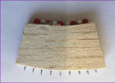
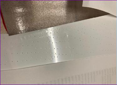
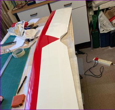
So, it had to be film over film. For anything other than a small overlap area, this is a sure fire recipe for getting air bubbles so I set to with my home-made perforating tool to pierce the whole area which was to be covered by red film. Unlike the soothing feel of popping bubble wrap, I must admit that I found the rather tortured popping of the taut covering somewhat stressful. However, all was well and, although there are some bubbles, they are very small and I'm happy with the overall look.
Fuselage covering proceeded in the usual order (back to front, bottom to top, so that seams face rearwards or downwards), slightly modified by the need to ensure that the overlap areas were red over white rather than the other way round. Because the tailplane is sheeted, the sunburst pattern could be achieved without large overlaps so there was no need for the perforating tool.
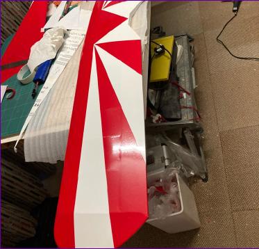
The upper wing was tackled in much the same way as the lower wing, with the perforating tool used to prepare the way for the red sunburst pattern.
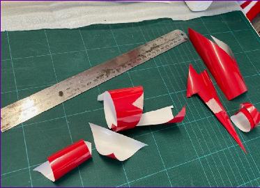
I was just beginning to feel confident that there was enough of the red film when I made a serious mess of covering the hatch, to the extent of having to take it all off and start again. However, by then there was only the cowl to do and the red flashes on the ailerons and tailplane. With a bit of careful planning, I got it all done. Just - the photo below right shows all that was left!
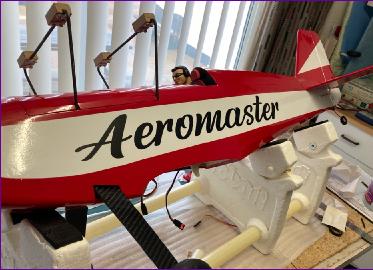
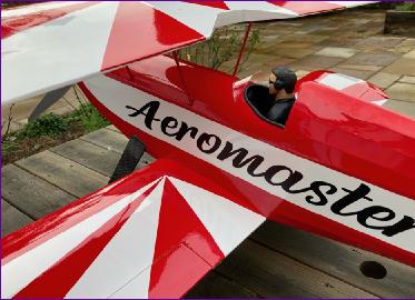
A suitably stern looking pilot was fitted, with a few bits of red foam for a seat back and headrest and a clubmate kindly produced the cut vinyl 'Aeromaster' decal for me.
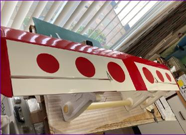
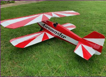
The model from which I cribbed this colour scheme had a chequerboard pattern on the underside of the wings. I really couldn't face that job so instead stuck a few circles of red vinyl on the underside of the lower wing, just to make sure that the model looked very different from underneath.
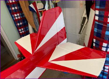
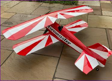
So, after daubing a bit of paint on the cabane wires, the model was pretty much finished.
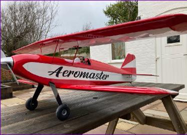
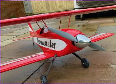
So, one day before the Covid-ridden year of 2020 draws to its dismal and welcome conclusion, the model was taken outside for a final photo call and power checks. As always at this stage, I'm aware of all the little things that could have gone better but I must admit that I'm pretty pleased with how it has turned out. As I've been preparing this diary entry, I've just heard that, from midnight tonight, we're going to join the 60% of the country effectively locked down by tier 4 Covid restrictions. I've therefore got no idea of when this model might get flown. However, I will keep looking at it as a bright and sunny sign of hopefully better things to come. After all, the other announcement today was that a second vaccine has been approved, so we live in hope!
Well, April 2021, and with the Coronavirus restrictions at last easing, the Aeromaster has now flown. I'd balanced the model a little forward of the position marked on the plan, and I'm glad I did. The handling is pretty well neutral and the elevator response very lively. With reduced elevator travel (and a bit more expo), I'm now happy with it's behaviour in pitch. Roll response by contrast was sluggish. Increasing the travels got the model rolling to the left at an acceptable rate but right hand roll response was still somewhat lacking. I had read some reports recommending ailerons on both wings and I'm now beginning to think that I should have taken that route.
A little confession: I'd noted before covering that there was a slight warp on the lower wing. I tried to straighten this out as much as I could during covering but the wing structure is very stiff and, unsurprisingly, now that the covering has settled, the model neeeds visible right aileron trim for straight and level flight. I'm reluctant to contemplate retro-fitting ailerons into the upper wing and still less enthusiastic about opening up the lower wing to tackle the warp. I am wondering whether the effect of the warp is all the worse because it is in the same direction as the propeller torque. I've therefore ordered a reverse pitch propeller so at least the effects of the torque and warp will tend to counteract rather than reinforce each other. If this proves to help, I then only have to butcher that lovely aluminium spinner cone to accommodate the left-handed prop!
August 2021 The Aeromaster has now chalked up some 23 flights, so I can report on the effect of the reverse pitch propeller. Rather than butcher that aluminium spinner, I swapped it for an old nylon red one which was easily re-worked to accommodate the left handed prop. After re-trimming the model, the roll rate was re-assessed and I'm delighted to report that it now rolls happily in either direction and at more or less the same rate. although the Aeromaster is now very pleasant to fly, if I were to start again, I would definitely fit ailerons on both wings. However, I'm happy to keep the model as it is and accept that 'twinkle' rolls are not in its repertoire. The other thing that I have to remember is that this is the only model I've got that can swing hard to the right at the start of the take-off run!