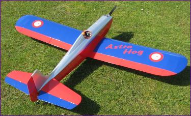
After building three scale twins in succession (the Sealand, Rapide and Welkin), I was in need of a change and happened across this design, which dates from the 1950's and was the first successful R/C aerobatic model. Originally designed by Fred Dunn, the Astro Hog has been kitted by Flair in the UK and, somewhat later, by Sig in the USA (pictured above). The kit versions (especially the Sig) include various changes to the construction methods and also to the design, but the strong character of the original still shines through. Long before these kits were produced though, a version of Fred Dunn's plan was published by the Aeromodeller Plans Service and I was delighted to find that this is still available through X-List plans, so that is where I decided to start.
My Hog of course, would be electric. In the weeks waiting for the plan to arrive, various thoughts and ideas were shared with my clubmates, including the possibility of including a dummy i.c. engine. I favoured vandalising a real engine, whilst others suggested building a dummy engine from scratch - and one of them has indeed subsequently done this. Eventually though, remembering that this project was intended to give me some respite from the stress of building scale models, I decided to banish such pursuit of authenticity and instead concentrate on deciding what modifications I wanted to make to the design. The main changes made in the Sig version were the use of strip ailerons, raising the position of the tailplane, and adopting a tricycle undercarriage layout. The last of these is sheer heresy and, perhaps in recognition of such reactions, Sig did include the option of reverting to the taildragger layout.
The raised tailplane does look better to my mind (the original, like the wing, was rubber banded onto the bottom of the fuselage), so I will go with that. However, I am hoping this will be a nice model for shooting lazy touch and go circuits so I wanted to add a bit of interest by fitting flaps. This rules out the strip aileron option.
The other change recommended by other Hog builders, was a reduction in the dihedral angle. This too looked like a good idea, remembering that, when the original was designed, R/C equipment did not offer the sort of precise proportional control we have come to expect today, so inbuilt stability was an essential feature of any successful design.
Not long after the plan arrived, The Woodspring Wings model show came around, so I was able to buy a motor, some servos and a selection of balsa wood which provided the incentive to clear a bit of space in the workshop and lay out the plans.
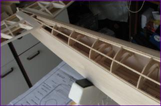
July 2009 The wing of the Astro Hog has a constant chord so basically, all ribs are the same. This made a very welcome contrast to the tedium of cutting out the wing ribs for the Rapide, and I could feel my 'Scale Respite Therapy' programme beginning to work already!
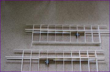
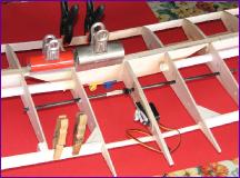
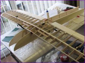
This first picture shows the basic wing structure, with paper tubes fitted to take the aileron servo leads. You can also see the beech blocks for mounting the undercarriage. These are fitted a little further forwards than marked on the plan, to try to limit the forward rake on the legs.
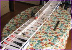
From here, it was a case of doing as much as possible before joining the wings. This included laminating the wing tips and sorting out the flap and aileron linkages. Then the dihedral braces were cut out and a series of dry fitting tests begun.
Here you can see the wingtips, which were laminated in situ, still taped up - the glue took a long time to dry under the masking tape. I also opted to fully sheet the ailerons and flaps, the alternative being 44 cap strips less than an inch long - not my idea of fun!
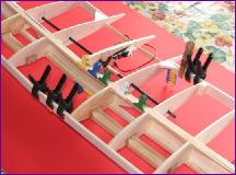
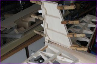
The next sequence of pictures shows the jigging arrangement for joining the wings - foreign language dictionaries do have their uses! The close-ups show the flap driver rod threaded into position and the flap servo mounted through the rear portion of the central ribs, which have not yet been glued in place.
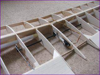
With the wings joined, the centre ribs were glued in place then the outer bearings for the flap driver rod (a leftover piece of carbon tube) could be precisely aligned and fixed. The bearings are spares from a Tamiya car kit of many years ago. I used a nylon bearing in the centre rib and a couple of flanged copper ones in the second rib of each wing panel. Three servo horns were epoxied onto the carbon rod, the end float being taken up by lengths of fuel tubing and spare inserts from APC propellers - all in all, a satisfying bit of recycling.
Although there is still a lot of work to be done on the wing, I put it to one side for now, to make a start on the fuselage.
By the end of the month, two fuselage sides were beginning to take shape.
August 2009
With two fuselage bulkheads cut out, fore and aft of the wing seat, I was able to clamp the two sides together and offer up the wing for the first time.
Having joined the fuselage sides, I wanted to sort out the wing fixing next so I got on with sheeting the trailing edge section. However before the leading edge could be done, the undercarriage had to be finalised.
Wire bending is not one of my strong points but, having received much help and advice with the Welkin u/c legs, I decided to put what I had learned into practice and have a go. The legs are from 5/32in piano wire and I am very pleased with the result. Mindful of the Chorus Gull's tendency to bounce, I deliberately kept the legs as short as possible and mounted the bearer blocks a bit further forward to minimise the forward rake on the legs.
It was quite a delicate task relieving the lower leading edge sheeting to make way for the undercarriage, but at last the wing fixing could be sorted out.
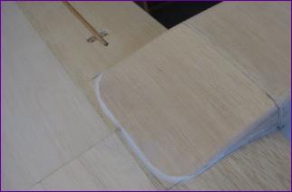
You can see though that the centre section sheeting is still missing. This is because I wanted to arrange for the flap and aileron servo connections to be made automatically when the wing was attached. After a lot of head-scratching, I decided that the best place for the connector was over the leading edge of the wing.
I have used the green Multiplex connectors for this purpose before but the challenge is always working out a way to mount the connector halves firmly enough for them to be engaged and separated whilst still ensuring that the two parts will align properly when the wing is fitted.
On the left is the arrangement I came up with (just dry fitted at the moment). The socket is to be solidly mounted in the bulkhead, supported by the 5mm balsa plate nearest to the camera. The plug will be glued to a mounting plate made up of two pieces of 1/16 ply visible immediately behind the bulkhead.
This mounting plate is attached by two screws though oversize holes to the piece of 1/8 ply and supporting balsa wedges glued onto the wing. The screws are not driven fully home so the plug and its mounting plate can move a little laterally and vertically to allow the connector halves to align - and also to avoid putting side loads on the connector if there is any movement of the wing in its seat.
Well, that's the theory. However, wiring was delayed due to lack of an extension lead so meanwhile, a start was made on the tail surfaces. The tailplane is initially built flat, then the spars fitted top and bottom and the ribs built up in front and behind the spars. This adds up to over 100 pieces of wood! The result is undeniably strong. It is though somewhat overbuilt - I should have used 1/16in balsa for the ribs and thinned the spars somewhat.
Elevators are 1/16in core with balsa 'wedge' ribs top and bottom, joined by a wire joiner to an internal elevator horn. The rudder is two skins of 1/16in balsa over a simple framework and uses a conventional horn, tailwheel and snake.
By now the missing extension lead had arrived and the plug and socket were duly wired up and tested. Although the wiring was fine, I managed to strip the gears on the flap servo during the test. Since I had almost covered the servo in and hard wired it to the plug, this was more than a little frustrating - serves me right for trying to get away with a nylon geared servo, I suppose. With the wiring duly checked, the wing mounted half of the connector was glued in place but I delayed fitting the fuselage half to minimise the wear and tear on the connector as the wing is repeatedly fitted and removed during the rest of the build.
Rudder and Elevator servos were mounted on the fuselage side, to be accessed via the large cockpit hatch.
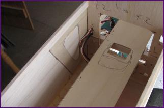
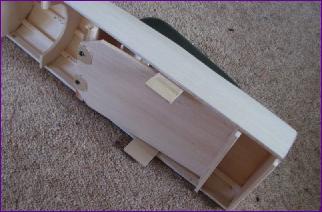
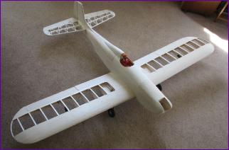
At last it was time to put the model together and stand it on its wheels for the first time. It was also possible to get a rough idea of where the battery would have to go. As expected, it will have to go a good bit further forward than planned, due to that over - engineered tailplane.
As you can see from the picture below right, the flap linkage is still accessible at this stage but will eventually be covered in, as will the aileron servos.
I just need to work out a sequence for connecting and hinging the various flying surfaces before everything gets hidden away.
With just one more day of August remaining, I made a start on the turtle deck framework, but found I couldn't get very far until the tail surfaces were glued in place.
It seemed a good idea to get a bit more done on the front end before doing that - and anyway, I still can't quite visualise how the fin/tailplane/fuselage joint is going to work!
So, the last act of the month was to make and fit the firewall.
At times, it has seemed as if I have been really putting in the hours on the project yet not really getting on all that quickly. However, the process of putting the month's diary entry together has made me feel that it is going pretty well really - might even get to the covering stage next month perhaps?!
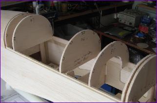
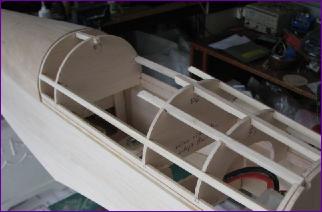
September 2009 More pictures than words this month, I think, so first the underside of the fuselage. . .
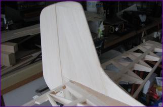
Then back to the turtle decking. . .
Then the fin. .
. . and rudder. . .
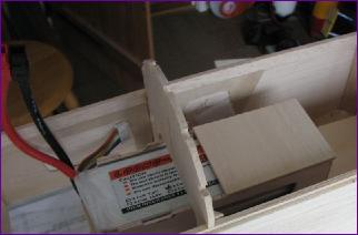
Battery tray. . .
.. and box. . .
Time then to make a start on the hatch.
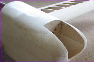
Headrest and underwing fairing
Hatch retention is by a wire spring at the front and ply 'squeeze plates' towards the rear.
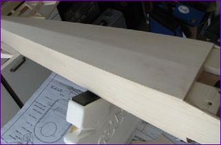
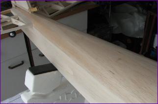
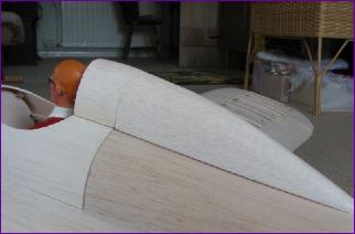
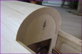
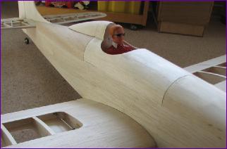
Finally the block balsa around the nose was sanded to shape - a messy business! This blockwork supported the engine bearers on the original and also served to absorb engine vibration. It is really redundant on an electric version but the shape of the nose is very characteristic of the 'Hog' so, I went with it.
So, time to put the airframe together one last time before getting out the covering iron.
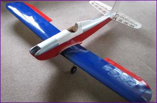
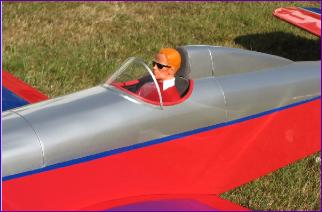
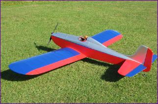
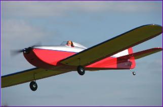
I was determined to cover this model from the leftover pieces of Profilm from previous projects. However, when I started to assess how much there was of each colour, it was clear that this was going to be a real challenge. Eventually the top of the wings were (almost) covered in blue (the red inboard section was by necessity rather than choice!) I had a very similar amount of yellow, so that was used on the underside of the wings. There was insufficient red to complete the fuselage, hence the two tone red/silver. Finally there wasn't enough blue and yellow to do the tailplane so it has a reversal of the wing's colour scheme - red for the fixed surfaces and blue/yellow for the elevators.
Considering all the various constraints, I don't think it looks too bad.
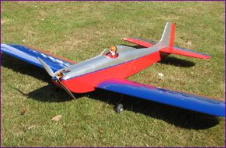
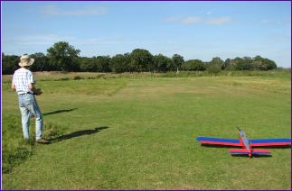
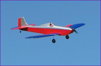
Unusually, the model was completed in the middle of a settled spell of weather - perfect for a maiden flight. So, off to the field, a few more photos, a quick range check and there was nothing for it but to line it up on the runway and go.
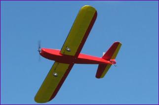
With a finished weight of around 5lb 8oz and around 800 watts of power on tap, the model has a wing loading of only 15.5oz/sq ft so, as you can imagine, it cruises on practically no throttle and will fly round loops as large as you like - very nice.
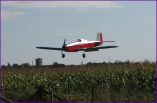
Unfortunately, the motor developed what I fear is a bearing knock after the first couple of flights so there might be a short break before I get to know the Hog better. So far though it promises to be a very useful addition to the hangar.
Postscript: Having now chalked up a dozen or so flights on the new motor (replaced without quibble) the Astro Hog is performing very well. I even got around to 'stickering it up' a bit.
 This first picture shows the basic wing structure, with paper tubes fitted to take the aileron servo leads. You can also see the beech blocks for mounting the undercarriage. These are fitted a little further forwards than marked on the plan, to try to limit the forward rake on the legs.
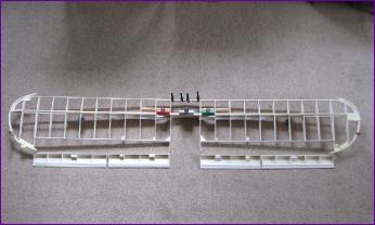
 With the wings joined, the centre ribs were glued in place then the outer bearings for the flap driver rod (a leftover piece of carbon tube) could be precisely aligned and fixed. The bearings are spares from a Tamiya car kit of many years ago. I used a nylon bearing in the centre rib and a couple of flanged copper ones in the second rib of each wing panel. Three servo horns were epoxied onto the carbon rod, the end float being taken up by lengths of fuel tubing and spare inserts from APC propellers - all in all, a satisfying bit of recycling.
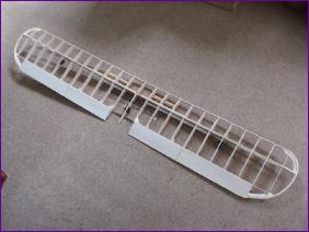 Although there is still a lot of work to be done on the wing, I put it to one side for now, to make a start on the fuselage.
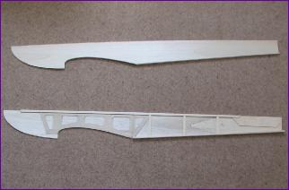
 With two fuselage bulkheads cut out, fore and aft of the wing seat, I was able to clamp the two sides together and offer up the wing for the first time.
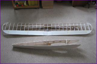 Having joined the fuselage sides, I wanted to sort out the wing fixing next so I got on with sheeting the trailing edge section. However before the leading edge could be done, the undercarriage had to be finalised.
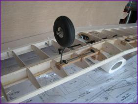 Wire bending is not one of my strong points but, having received much help and advice with the Welkin u/c legs, I decided to put what I had learned into practice and have a go. The legs are from 5/32in piano wire and I am very pleased with the result. Mindful of the Chorus Gull's tendency to bounce, I deliberately kept the legs as short as possible and mounted the bearer blocks a bit further forward to minimise the forward rake on the legs.
 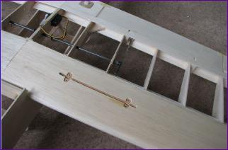 It was quite a delicate task relieving the lower leading edge sheeting to make way for the undercarriage, but at last the wing fixing could be sorted out.
 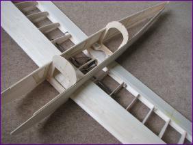 You can see though that the centre section sheeting is still missing. This is because I wanted to arrange for the flap and aileron servo connections to be made automatically when the wing was attached. After a lot of head-scratching, I decided that the best place for the connector was over the leading edge of the wing.
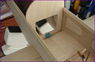 I have used the green Multiplex connectors for this purpose before but the challenge is always working out a way to mount the connector halves firmly enough for them to be engaged and separated whilst still ensuring that the two parts will align properly when the wing is fitted.
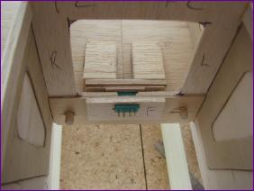 On the left is the arrangement I came up with (just dry fitted at the moment). The socket is to be solidly mounted in the bulkhead, supported by the 5mm balsa plate nearest to the camera. The plug will be glued to a mounting plate made up of two pieces of 1/16 ply visible immediately behind the bulkhead.
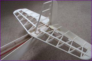 This mounting plate is attached by two screws though oversize holes to the piece of 1/8 ply and supporting balsa wedges glued onto the wing. The screws are not driven fully home so the plug and its mounting plate can move a little laterally and vertically to allow the connector halves to align - and also to avoid putting side loads on the connector if there is any movement of the wing in its seat.
 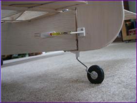 Elevators are 1/16in core with balsa 'wedge' ribs top and bottom, joined by a wire joiner to an internal elevator horn. The rudder is two skins of 1/16in balsa over a simple framework and uses a conventional horn, tailwheel and snake.
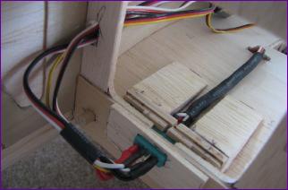 By now the missing extension lead had arrived and the plug and socket were duly wired up and tested. Although the wiring was fine, I managed to strip the gears on the flap servo during the test. Since I had almost covered the servo in and hard wired it to the plug, this was more than a little frustrating - serves me right for trying to get away with a nylon geared servo, I suppose. With the wiring duly checked, the wing mounted half of the connector was glued in place but I delayed fitting the fuselage half to minimise the wear and tear on the connector as the wing is repeatedly fitted and removed during the rest of the build.
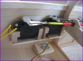 Rudder and Elevator servos were mounted on the fuselage side, to be accessed via the large cockpit hatch.
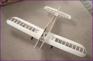 At last it was time to put the model together and stand it on its wheels for the first time. It was also possible to get a rough idea of where the battery would have to go. As expected, it will have to go a good bit further forward than planned, due to that over - engineered tailplane.
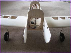 As you can see from the picture below right, the flap linkage is still accessible at this stage but will eventually be covered in, as will the aileron servos.
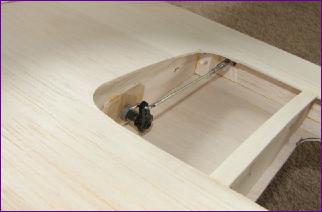 I just need to work out a sequence for connecting and hinging the various flying surfaces before everything gets hidden away.
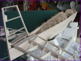 It seemed a good idea to get a bit more done on the front end before doing that - and anyway, I still can't quite visualise how the fin/tailplane/fuselage joint is going to work!
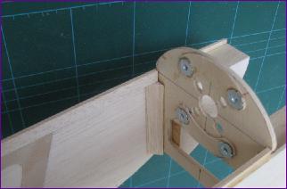 So, the last act of the month was to make and fit the firewall.
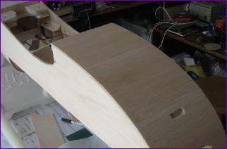
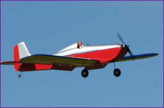
 Postscript: Having now chalked up a dozen or so flights on the new motor (replaced without quibble) the Astro Hog is performing very well. I even got around to 'stickering it up' a bit.