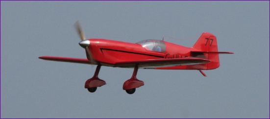
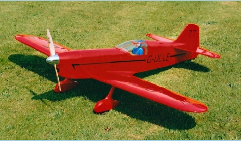
This model is a semi scale rendering of the Percival Mew Gull and appeared as a free plan in the February 2002 edition of RCM&E.
As presented, the plan is for a .40 - .61 sized engine (although the review model used a .90!) and has a quoted all up weight of 7.75lb. For a 61.5inch span model, this seemed to me somewhat heavy and I was surprised to read that it apparently flew well at this weight. Looking at the plan, it is hard to see how it could weigh so much (a lot of noseweight, perhaps?) and I convinced myself that, even with 16 - 20 cells on board, an electric version should still be well within that weight limit.
I contemplated various power options and the longer I thought about it, the more expensive the preferred option became! Eventually I came back down to earth and the recently repaired Aveox 1406/4Y sitting on the bench doing nothing, was chosen. Decision made, I ordered an MAT belt drive gearbox, bought a load of balsa wood and cleared a space on the workbench.
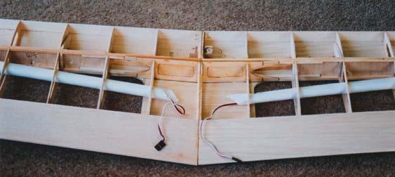
Wings Apart from thinning down the spars and using laminated rather than sheet balsa for the wing tips, there wasn't a lot to be done to the wing. I used 1/16 balsa for the ribs and cut lightening holes in the ribs and the aileron cores, but beyond that, it was really a case of using light wood - one of the benefits of converting a plan rather than a kit. The 1/8 ply servo mounts were omitted and the servos mounted through the ribs The ply doublers around the undercarriage mounting blocks were also thinned - hopefully not too much.
Fuselage (part 1) Lots more scope for change here: Practically all components were thinned down at least one size, and all formers aft of the leading edge were made from balsa rather than Liteply. A top hatch was also sketched in behind the firewall on the basis that the battery would probably have to go somewhere here. Although, if my theory about the i.c. version needing lots of noseweight is right, it is possible that the battery might have to be dropped in at an angle through the firewall into the lower cowl area. This uncertainty over the battery location, plus the fact that I didn't yet have the gearbox to hand, meant that the firewall and all things forward would have to wait a bit.
Using the published dimensions of the gearbox, I was able to establish that the firewall could be relocated further forward (which gave a bit more flexibility over battery location) so I cut out a pair of fuselage sides and built just enough of the fuselage to be able to attach the wing as an alignment reference. The tail end was then pulled together and work started from that end.
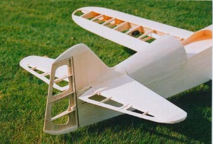
Tail On the DC3 I fitted the rudder and elevator servos under the tailplane and it seemed a good idea to do the same with the Gull. The only snag was that I couldn't work out a neat access hatch arrangement. One thing led to another and before I knew it, I had talked myself into making the tail surfaces detachable. This of course led to much head scratching and complication, but the final arrangement works well and I don't think it has negated all the weight saving.
The solid sheet tailplane and elevator were of course replaced with built up components, the fin and rudder being built more or less as per plan. Because the rudder is attached both to the fin and the lower fuselage, it has to be removed before the tail and fin can be lifted off. Pinned hinges were therefore used. Fin/tailplane fairings are 1/16 sheet rather than shaped block.
Fuselage (part 2) With the tail end sorted out, the rear fuselage was sheeted in with 1/16 balsa, until I came to a couple of things that I usually put off for as long as possible - the cockpit canopy and the wing fairings. Time to take a few more photos and consider what to do next.
From this point, the construction order was a little unusual. With the gearbox still delayed, the flying surfaces were covered and, yes, the wing fairings and canopy had to be tackled. I even made a start on the spats. However, I couldn't find any suitably slim wheels, so I opted to make my own by the Mike Payne method.
Then I was offered the loan of a demo model of the gearbox so that I could get on with building the front end of the Gull. A trial balance indicated that the battery may indeed have to be located well forward into the nose area (although the cg position marked on the plan does seem a long way forward). I therefore made a big hole in the firewall before fitting it.
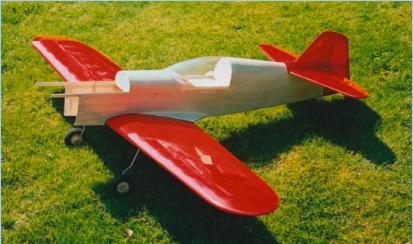
The MAT belt drive gearbox is made for beam mounting and also has holes for bulkhead mounting. After much thought, I went for a combination of both. The gearbox is mounted onto a bulkhead and this is firmly linked to the original firewall by two beams which fit snugly against the gearbox, but are not actually attached to it. This arrangement enables the top of the fuselage, forward of the access hatch, to be fixed, a small detachable lower cowling giving access to the motor and gearbox. For the moment, the beams are not glued in position - just in case a change in powerplant is needed at some point.
The picture shows the general arrangement. The top of the nose section was planked in with 2.5mm balsa to blend in with the aluminium spinner, and the lower fuselage sheeted in up to the mounting bulkhead. A 'chin cowl' was then made out of 6mm balsa.
As I was cutting a neat cooling hole in the front of the cowling, I realised that there was nowhere for the air to get out. Cutting exit holes at the rear of the cowling would let the air out before it even reached the motor, so that was no good. In the end, I cut a hole in the bottom of the fus behind the wing, so the battery and ESC should hopefully see a bit of draught too.
With the fuselage complete and covered, with just the cockpit to fit out, the gearbox eventually arrived. This gave me the impetus to find and fit a pilot, finish off the instrument panel and do a power test.
Power Limits Reading the instructions with the MAT gearbox, I realised that there was a 20,000 motor rpm limit on the belt drive. The next step was to look at the Aveox web site to see what the current draw would be at 20,000rpm on 16 cells. The answer was about 27amps. On the face of it this seemed quite reasonable but Aveox claim that, at this cell count, the motor should only be propped to draw 18amps at full throttle for sport use. At this current, the 20,000rpm limit is well and truly blown, even on the ground and, once the model gets moving will only get worse. First priority though, was to check out the model so a 13 x 8 Master Airscrew prop was fitted, which gave a static maximum current draw of just under 24amps, turning at 6,200rpm. This equates to 22,320 motor rpm, so care would be needed with the throttle!
At this point, the model was complete apart from the spats and trousers. As a way of putting off this job a little longer I opted to fly the model first, on the grounds that I could at least check out whether any adjustment to the forward rake of the undercarriage was needed.
First Flights After all the usual checks, the Gull was lined up and the throttle opened. The tail came up pretty well immediately and it was easy to keep straight. Once airborne, I eased back on the throttle and the model continued to climb steadily. It was very pitch stable (suggesting that the marked cg is indeed a bit on the conservative side) and no elevator trim adjustment was needed. It did though need a good bit of left aileron trim, which was a bit of a puzzle. Once trimmed, the model handled well but, when the throttle was opened, there was a rough note to the motor which I suspect was the belt protesting at the overspeeding. As a result, apart from a gentle half throttle roll, no aerobatics were tried.
Landing was uneventful and, all in all, first impressions were of a well-mannered aeroplane. A second flight was pretty much a repeat of the first, so it was back home to sort out the powerplant, the aileron trim - and the spats and trousers.
Finishing Touches After checking out the lateral balance, I was forced to the conclusion that the need for aileron trim must be down to the wing, even though various people had eyed it up at the field and pronounced it to be straight. With the wing inverted on the bench (It still had the u/c legs on at this stage), careful measurement did indeed reveal a slight twist, so there followed some complicated gymnastics with one wingtip gripped between my feet, the centre between my knees, one hand twisting the other tip and the other hand weilding the heat gun. It was at this point that any worries I may have had about overdoing the lightening of the structure were quashed - this is a very stiff wing! However, after a while, I convinced myself I had effected some improvement so it was off to the model shop to buy a selection of 14inch props.
At this point, the English Summer took a break and we were lashed by a week of rain and gales, so eliminating my very last excuse for putting off the dreaded spat building. Like so many things, once I forced myself to face up to the job, it wasn't as bad as I feared. However it did seem to take forever. The result though is well worth it, as I hope the pictures show.
Take Two With a 14 x 10 Zinger wooden prop, the static rpm came down to 5,500 (equivalent to a motor rpm of 19,800) and the current draw went up to just over 27amps. This is something like the setup I would like to end up with. However I took pity on the motor at the last minute and dropped down to a 14 cell pack which gave....... well, exactly the same in fact! Admittedly the 14 cell 2400 pack was fresh off the charger but this does go to show that my 1700mah 16 cell packs are beginning to show their age.
So, with the 14 cell 2400mah pack on board, the model weighed in at a shade under 6lb, complete with spats. The performance with this setup is pretty sprightly, large loops being possible from level flight. The need for aileron trim seems to have gone away, so my wing warping session clearly achieved something. At present I am still progressively increasing the flight duration, and it is clear that 8 minutes of gentle aerobatic flight is easily possible, so maybe the motor isn't working too hard after all. Time will tell.
I am well pleased with this project so far and will fly the model for a while in this configuration. If I do eventually feel the need for more power, it is nice to know that the model is curently 28oz below the weight of the i.c. prototype!
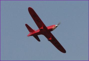
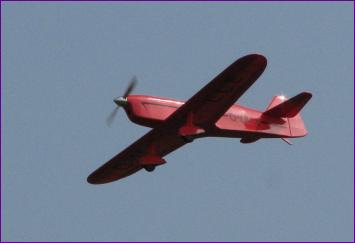
Seven Years On! Still with the same powerplant, but converted to run on a 4s 3700mah LiPo battery, this model continues to give good service. The gear ratio has been dropped from 3.6:1 to 3:1 and the prop changed from a 14 x 10 to a 14 x 8. These changes, together with the weight reduction of over 1lb from the battery technology update, have led to a very sprightly performance that lives up to the racing pedigree of the full size Mew Gull on which this model is loosely based. As you can see from the new header picture to this article and the two pics below, this is a design which looks good from any angle.
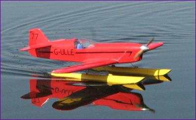
Ten years on, and the Chorus Gull has been granted a new lease of life as a floatplane! Read all about it in this article.
 From this point, the construction order was a little unusual. With the gearbox still delayed, the flying surfaces were covered and, yes, the wing fairings and canopy had to be tackled. I even made a start on the spats. However, I couldn't find any suitably slim wheels, so I opted to make my own by the
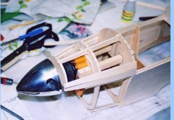
 Ten years on, and the Chorus Gull has been granted a new lease of life as a floatplane! Read all about it in