|
   
Lightning Strike
by Trevor Hewson
An edited version of articles originally appearing in Sloping Off (the newsletter of the Christchurch and District MFC) and also in Radio Control Scale International (May/June 1998)
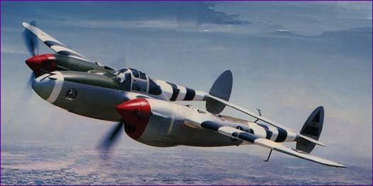
The full size specimen (Air Classics August 1996)
I'm not sure where my fascination for twin boom aircraft really stems from. Perhaps it was those teenage days when I would be distracted from my control line exploits by the early jets, including the Vampire and Venom, ripping across the Lincolnshire skies. Anyway, at a club meeting, some photos of a Duxford air show were being passed around which included a picture of a P38 Lockheed Lightning. "Always fancied building one of those" I said idly, to which clubmate George said "I think I've got a plan for one somewhere" From such a chance remark this project was born.
The Plan
The plan turned out to be an RCMW 'freebie' published in two parts in 1988, by Gordon E. Whitehead. The size was ideal - 52" wingspan - and my enthusiasm grew as I read the article and admired the many photographs. The designer claimed good flying characteristics but reported some problems getting away from hand launches. Since the model was powered by a pair of OS15s this could hardly have been through shortage of power (I was planning to fly on one 7 cell battery!) so there was only one other explanation. Sure enough, the all up weight was a hefty 72oz - and I had to find room for another 14oz of battery.
The Re-plan
Comparisons with other 7-cell electric models indicated that 3lbs would be a good target, but could it be done? I had to lose 1lb 8oz and accommodate the weight of the flight pack!
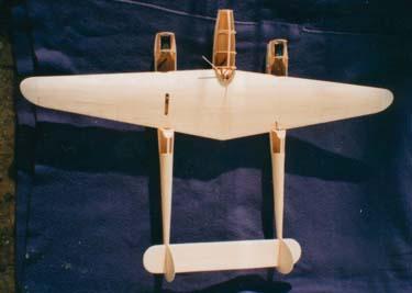
Examination of the wings showed little scope for weight saving. They are all built up, sheeted in 1/16" balsa. I reduced the rib thickness, changed the spar doublers from spruce to balsa and left out various reinforcing pieces on the grounds that the wing was going to carry a lighter load.
As designed, the model breaks down into a wing, two booms and a tailplane, all of which bolt together. By opting for a one-piece model a whole load of ply plates and other stiffening pieces can be dispensed with. However there is no getting away from the fact that this aeroplane has to carry around three fuselages instead of one and it was here that the lightness had to be added by the bucketful.
The Remodelling
The booms and the centre pod are elliptical in cross section and this is achieved in the original design by the use of ply formers and thick balsa sheets, mainly 1/2", that are subsequently sanded to shape. This approach was abandoned and instead 1/16" balsa was rolled round the tapered rear sections of the booms and 3/32" planking used where there were compound curves. Liteply was used for most of the formers, fretted out to become little more than hoops.
Next up for the crash diet was the tail section. First to go were the rudders, saving two sets of hinges, a servo and the (rather complicated) linkages. The tailplane structure could also be revised to allow the use of thinner skins and the fins and elevator would be built up rather than solid.
Apart from the wing, this had by now become essentially a scratch build project, the original plan being used as a valuable reference for outline and for former shapes. Little surprise then that the wing went together quite quickly but things then slowed down somewhat.
The Vital Urge
In between building sessions, I began to ponder just how to power the Lightning. With a 7 cell 1700mAh battery, I needed a set up that would deliver power reasonably efficiently whilst drawing no more than about 20 amps. (20 amps gives a theoretical flight duration of about five minutes). 7.2v Speed 400 motors become seriously inefficient at currents above about 7 amps, but the 6v Speed 400 will draw 10 amps quite happily, so two of these seemed to fit the bill.
However the 6v. motor revs somewhat higher than the 7.2v version and so will only swing relatively small props, typically 6" diameter. These would look rather lost against the generous section of the Lightning's booms and the idea of hanging a 21/4" spinner on the end of that slender motor shaft didn't really look very promising. So, shame about the weight, but gearboxes had to be used. After much experimenting, I established that using a 1.85:1 gearbox with an 8"x4" propeller gave me a current draw of 9.8amps, and 7800rpm giving a calculated thrust of 14.4oz. Two of these drawing just under 20amps should therefore give nearly 29oz of thrust which ought to cope with an all up weight of up to about 3lb 8oz., giving me a reasonable contingency against my original target of 3lb - even after allowing for the weight of the gearboxes.
Back to the Building Board
So now at least I knew what had to be fitted into the front end of the booms and, once I had located some spinners of a suitable shape, there was nothing for it but to get stuck in, so to speak. Eventually the booms took shape but the top front section could not be sensibly built until the wing was in place. I knew that, once the wings and booms were joined, things would become very unwieldy, so it was now a case of working out what else could be done before taking this crucial step.
Bits and Pieces
There turned out to be quite a lot of these! I won't bore you with the details of the tail - it was all quite conventional really. However, it seemed to take forever and, when I stopped to work out why, I counted over 80 pieces in the tail section alone! My main worry here was those large sub fins which, combined with the very slender boom section just in front of the tail, looked tailor-made for ripping the tail off on landing. A 1/32" ply core was included in each sub fin (full of lightening holes of course) and extended forwards into a slot cut in the boom. I decided to avoid the temptation to reinforce with glass on the grounds of weight.
Next were the cowlings. Again, no special difficulty but, having to make it up as I went along, it took longer than I expected and, with this model, your reward for solving such a problem is you get to build a second one.
At this point I was about to undertake the big wing/boom joining ceremony. Then I looked at those boom radiators. The plan gives no details of construction, the implication being that they are carved from solid. No chance! After due pondering, I concluded that these had to be planked in 1/16" balsa over a framework of formers - for which there were no drawings. This time you get to make four of them!
By now, the principle of putting off the boom/wing joining had assumed almost religious proportions - so I started on the centre pod. This has to carry the battery and the tapering shape limits how far back the battery can go. An attempt to predict the cg concluded that the battery had to go about 0.5" further back than was possible. However, 0.5oz extra on the tail would overcome this - so perhaps the boom/tail joint will get glassed after all.
After another spell of planking (the centre pod is all compound curves) I again reached the point where I could go no further until the pod was fitted to the wing. So - the time had come. It had to be done!
Joining Up
Having done so much worrying up front, the actual mating of the booms to the wing was almost an anticlimax. Everything lined up first time and so the way was clear for the next exciting step - more planking! The only complications on planking the top of the booms were the odd shaped cutouts for the superchargers and the care needed to ensure that the planking, after sanding, would blend smoothly into the spinners. The elevator linkage also disappeared forever at this point - fortunately I did remember to thread the pushrod down the boom before joining it to the wing!
So onward to the centre pod. You've got the idea by now, yet more planking. Shaping the noseblock and the tapered block at the rear came as a pleasant interlude. Once the planking was sanded smooth, the hatch was cut out and, for the first time, I could find out for sure whether it was actually possible to insert the battery. Fortunately a seven cell 1700 pack slid in beautifully, but I was somewhat disappointed to find that an eight cell pack was just too long to negotiate the corner. Another contingency bites the dust!
The Office
Scale models have to have pilots. They really do have to, don't they? Actually the pilot himself is no problem, I just subcontract the painting task to David. But, if David's handiwork is to be admired as it deserves to be, then I had to make a transparent canopy. Now, if you are faced with this problem on your model please feel free to pick my brains. I can't tell you how to do it, you understand, but I do have full details on several methods that don't work! Eventually, six plastic bottles and two acetate sheets later, I succeeded in moulding the three sections of the canopy separately. At the time of writing, these sections are joined with masking tape and, whilst the shape and fit of the parts are satisfactory, I have yet to decide how they are to be joined together - or indeed how the canopy is to be attached to the model.
Finishing
I used to think that "finishing" meant something like "approaching the end". Wrong! The task of obtaining the desired finish on a surface can be a very time consuming one, which is why I use film coverings wherever possible. However, the prospect of trying to persuade Profilm to follow the contours of the boom radiators was somewhat daunting. What's more, the full size P38 which I had chosen to copy had invasion stripes (seemed like a good idea at the time, from a visibility point of view). The idea of getting the black and white film to meet in a straight line on a compound curved surface was enough to persuade even me to reach for the paint pot.
But before the paint, comes the preparation. In the interest of saving space, to learn how I got on with this, just read the bit about moulding canopies again, substituting coats of sanding sealer for plastic bottles! Again, for a small fee, I can tell you exactly what not to do! Eventually, enough was enough and several coats of white enamel were applied. The effect is not great and, with the benefit of hindsight, I think I would have been better off tissue covering the area to be painted.
Ah well, on to the instrument panel. And then there's this problem with joining the canopy. And I ought to glue the tail on at some stage......
The P38 continued to dominate the workshop for a further three months. It was finished mainly in silver grey Profilm, with Solarfilm, Protrim and Solartrim all being used in places depending on the precise colours available. Out of interest, I kept a tally chart and notched up a final score of 154 pieces of film and trim on the finished model, in red, white, blue and black as well as silver.
The use of paint was minimised but I did paint the antiglare panels, cockpit interior and air intakes
You may recall that, after several abortive attempts, the canopy was finally moulded in three separate pieces using the plastic bottle and heat gun method. Two arches were laminated out of balsa and further slivers of balsa glued to the top of the fuselage pod to provide something for the front section to be glued to. The front arch was then positioned and the front section glued in place. This was followed by the pilot, rear arch, centre section and rear section, with some rather precarious arrangements involving a pair of pliers, rubber bands and several battery packs to apply pressure in the necessary places while the glue set. The one tip I would recommend is the use of Brasso on the scratches (before assembly of course). It doesn't actually remove the scratches but it does make them far less conspicuous.
After fiddling about with various details like air scoops, superchargers, cannons and lettering, it was time to sort out the installation of the receiver and speed controller and do a final check on the cg. This revealed that the model was nose heavy. With the battery as far back as possible, the cg was more than 1/4" forward of the recommended position. The good news though was that, with props and spinners fitted and battery installed, the all up weight came out at 3lb 2oz, giving a wing loading of 21.5oz/sq. ft. Pretty well on target.
With a bit of help from the computer, the model formates on the full size!
Firing up
Connecting up and switching on resulted in a warning "beep beep" from the speed controller to tell me the motors were armed and so I gingerly opened the throttle. At first all was well but, as the revs built up, vibration set in until, at around 6500rpm it was clear that something was amiss.
After checking for any obvious source of imbalance I came to the reluctant conclusion that the bearings in the Graupner gearboxes (which are only about 1cm apart) just couldn't cope with the combined mass of the propellor and spinner on the end of the output shaft. The prop drivers I was using were Graupner items which fitted snugly in the holes in the Graupner props without any need to bore them out. This meant though that there was not enough 'meat' for the gearbox shaft to extend into this part of the prop driver. I found another prop driver which slid further back on the shaft but, being a fatter item, needed the props to be reamed out. All attempts to find another similar prop driver failed and I ended up buying one for a larger diameter shaft and sleeving it with brass tube. I also bought two cheap spinners on the grounds that they were a little lighter than the Carl Goldberg ones and did not have a backplate behind the prop. The result of this meant that the propellor now fitted 1/4" further back on the shaft - so I had to move the motor/gearbox assemblies 1/4" further forward.
These modifications did not cure the problem completely but I could now run the motors at full throttle, experiencing some vibration as they beat together, but I deemed this acceptable.
Final preparations for flight included a quick current check (19.5amps) and sorting out arrangements for retaining battery and hatch in position. The latter was accomplished rather ingeniously I thought, by extending the piece of plastic snake inner forming one of the cannons on the nose.
Flight Time
This was a Special Day! It was Easter Sunday. It was to be the P38's maiden flight. It was also to see the first flat field attempt (after some cg exploration on the slopes) of Dave's Boulton Paul. Dave also had his new and unflown 50" electric Lightfighter. Add to this the maiden flight of the club trainer and the second attempt to persuade Neil's Robbe Gnat to go and you can see what I mean. In fact Jim's electric ducted fan MiG 15 was the most proven model present. How things change!
The P38 was readied and range checked. Jim confirmed that it felt comfortable (I had taken Derek's advice and stuck on a couple of patches of sandpaper to serve as finger grips) and did a quick run to check that the elevator felt more or less in trim. A last check on the wind direction and it was a case of open the throttle and throw it.
Now I was concerned to have room to abort the launch in a straight line if the forward cg or lack of power posed a problem and so Jim was well back towards the bushes ready for the launch. He took a long run and was more or less alongside me when he let go. I therefore had an unusual spectator's side view of the launch and I have to say it was perfect. As he let go I prepared myself for it rearing up or heading earthwards but nothing happened. The motors droned steadily and the Lightning just cruised on at the speed Jim had launched it, gently banking away to the left.
I was mesmerised - it looked great. It was doing so well by itself I was reluctant to interfere, but the bank angle was increasing so a touch of right aileron was applied. The turn continued and more aileron was needed to open the turn out into a respectable circuit, which was completed reaching about 25ft. The right aileron was held in for a second left hand circuit - up to about 60ft now, high enough to feed in some trim! After one more left hand circuit it was time to turn right. a few more circuits each way confirmed the safe and docile handling and the model was lined up to land. The approach was steady and the elevator was powerful enough to hold the P38 off and bleed off some speed and then it was all over.
Everyone agreed that the model looked great in the air. The rumble of the gearboxes and beat of the motors sounds appropriate too. Most surprising was the flying speed. I got the impression that from the moment the model left Jim's hand the speed never varied all through the flight. Scale speed is a difficult concept, but this model certainly looks like a scale model rather than an overdressed pylon racer. However it does seem to be a single speed aeroplane and I would have liked to have had a bit more power in hand.
The second flight was to prove more eventful. Again Jim gave a first class launch and the left hand climb out circuit was repeated, this time without the need to hold in opposite aileron. As the model turned into wind, again at 25-30ft, the right hand spinner flew off. I was still trying to decide whether to terminate the flight when Jim, retrieving the spinner, announced that the spinner had a propeller attached to it! "Oh" said Dave, "so it flies on one engine!". Realising belatedly that I had a potential emergency on my hands, I began a landing circuit. The P38 seemed far less concerned than I was and flew a normal apprach and a carbon copy of the first landing. On collecting the model though, one of the tail booms was found to be cracked. So, sum total of lessons learned:-
(i) Increase propellor pitch
(ii) Improve prop driver retention
(iii) Glass reinforce tail booms!
Whilst it is always disappointing to take a model home damaged, I felt that this first session had gone pretty well - I had learned a lot but, most important of all, the P38 looked so good and handled so well that all of the effort over the previous 10 months was well justified and I was more than willing to go the extra mile and tackle the problems that had come to light.
Rework time
The tailbooms were duly stripped, glassed and re-finished, flats ground onto the gearbox shafts to help the prop driver grub screws do their job, and two 8 x 6 props purchased. This time I chose Master Airscrew nylon props on the grounds that they were a bit more flexible than the grey Graupner ones and so more suitable for belly landings. They also turned out to be a few grams lighter so hopefully further easing the vibration problem which I feel was largely responsible for the prop throwing incident.
With one of each prop size fitted, I recorded 7,800rpm on the 8x4 and 7300 on the 8x6. According to ThrustCalc, this means that the 8x6 produces 1.6oz less thrust but gives a theoretical speed of 38mph compared with 27mph for the 8x4. Interestingly with 8x6s on both motors I could only achieve 6,900rpm! All seemed pretty smooth and the current draw was almost exactly 20a, so - all set for stage two.
The Waiting Game
Now, how often do you read in model reviews about delays caused by bad weather? You know the sort of thing, howling gales, torrential rain etc. Well, this was different. In mid April we were gripped by a Spring drought and the weather was set fair - and the ground was as hard as concrete! Ok, so I had glassed the tailbooms, but I felt I had to wait for things to soften up a bit before trying again. In the meantime I re-worked that clever cannon operated hatch release to be a combined hatch release and on/off switch and designed the mark two battery retainer (The balsa block used for the first two flights was dislodged both times on landing).
Stop Press
Mid May, some six weeks after the first outing, and once again the flight test crew assembled at Kings Park, this time augmented by Clive as video cameraman.
Jim again thrust the P38 smoothly into its intended element, and it was immediately clear that the change in propellor pitch had had a significant effect. The model accelerated steadily into a climbing circuit and there was a comfortable reserve of power. The P38 was put through a series of fast and slow turns of increasing tightness without any tendency to flick out, but no aerobatics were attempted. After three minutes, I called "landing", throttled back, entered the approach pattern - and immediately encountered lift! There was plenty of battery power left and so I was able to fly another circuit without drama and, at the second attempt, the Lightning came in for an easy landing.
Post flight inspection showed no sign of any stress on the tailbooms and the speed controller and battery were barely warm, so I would guess that the current draw in the air is well within the 20amp limit and should result in flights of over five minutes duration. Time will tell.
I was so pleased with all this that I could think of no further adjustments or improvements and so, on arriving home, the model went straight back into the rack, ready for next time. Five minutes later I took it down again, just to check that the grub screws in the prop drivers were still tight. Paranoid? Me? Never!!
11 Years Later
The P38 has undergone a bit of refurbishment and been converted to brushless motor / LiPo battery power - see here for more details.
   
|
|