January 2020 (Click here to return to part 1) Some of you may have spotted that the Petrel is no longer the newest entry in this section of my site. Having received a Phase 5e for Christmas, it seemed only right that I should get that assembled and flying before resuming the Petrel build (neither the workshop nor my brain have the capacity for more than one project at once).
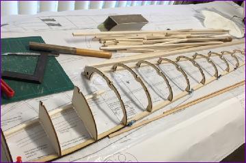
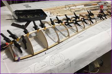
Once that was out of the way, the fuselage plan was laid out and, after a quick session with the balsa stripper, the first set of half formers could be dry fitted.
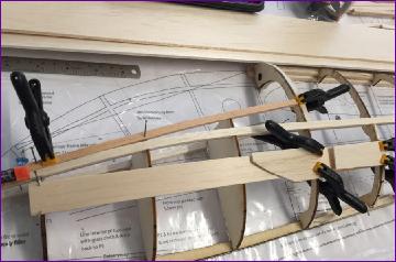
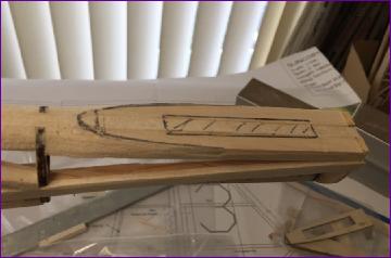
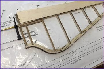
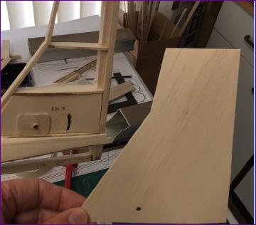
The Petrel fuselage is intended to be skinned with ply - 1/16in for the nose section, 1/32in for the rear. This results in a strong structure and a firm base for painting. However, as regular readers will know, I don't do paint, and ply is not the best surface for applying a film covering so I'm planning to use balsa instead. In a gesture to put back some of the lost rigidity, I beefed up the longerons from 6mm square balsa to a lamination of 3 x 6mm spruce and 3 x 6mm balsa. This modification brings its own problems though because the longerons bend downwards at front and rear.
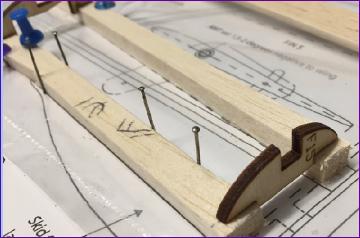
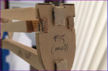
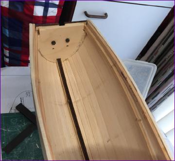
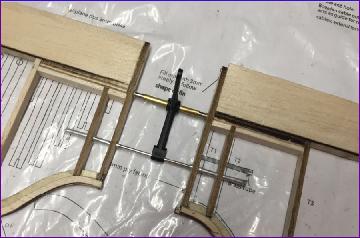
The first picture below shows how I cut a slot through the front section of the spruce component to help with the downward bend there. The situation at the rear is rather more perplexing. In the second picture below you can see the slot in F15 but the longeron drawn on the plan is drawn straight and so doesn't bend down to fit the slot! This problem was deferred by leaving out F15 or the time being. More later!
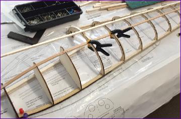
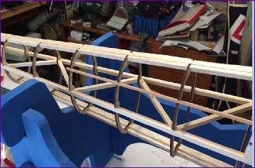
Having glued the formers in place, I fitted the keel doublers between them to give the formers a bit more support while fitting the longeron. The latter was fitted in two stages, first the spruce, then the balsa cap strip.
You can see from the pictures that there is a temporary keel piece through the middle of the cockpit area. The ply formers F2 and F3 are also temporary and have to be broken out later to open up the cockpit area to accommodate the pilot.
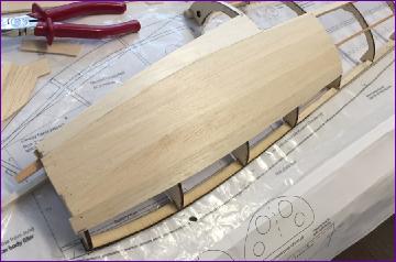
The spruce cockpit rail is fitted next. This was steamed roughly to shape first, to reduce the stress build-up. The front section was then planked with 3mm balsa. The idea of this is to lock this part of the structure in shape before it is lifted off the board. This is all very well, as long as the shape that gets locked in is the right shape!
Unfortunately, as you can see from the pic below, at some point in the proceedings F1 had become detached from the temporary centre keel. Sure enough with most of the planking now in place, this half shell was remarkably rigid and, with only a bit of 6mm balsa to pull against, there was no way of correcting it.
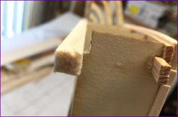
I couldn't face the prospect of ripping off the planking so temporarily bolted the two halves of F1 together with the gap between them so that at least I would be building a symmetrical fuselage. Whether or lot the nose could be pulled in afterwards was added to the 'deferred issues' list.
So, the second half of the fuselage was built onto the first, then the nose section was planked up to the same level as the first side. Once the glue had thoroughly dried, the bolts were removed and the gap in F1 could be seen clearly.
The front portion of the temporary cockpit keel was broken off to get it out of the way and an exploratory squeeze indicated that the gap could be closed with firm pressure but it would need more than a few rubber bands and bits of masking tape to hold it there.
A slightly smaller, one piece, version of F1 was cut out, suitably drilled, and, after a trial fit, glue was applied and the bolts put in place once more.
Breathing a huge sigh of relief, the remainder of the nose planking was completed.
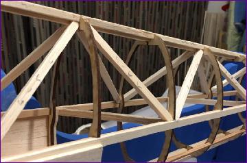
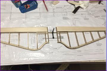
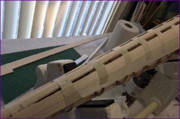
Fitting all those fuselage diagonals might in other circumstances have seemed tedious but in fact it proved a nice stress reliever after the drama with the front end.
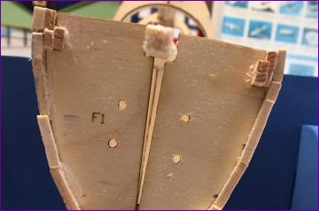
Time now to return to the other deferred problem, that of the rear former F15. Looking at the way the tail end gets built up to form a base for the fin, it was clear that there was no point using the round-topped F15 halves supplied. Instead a one-piece F15 was cut out and glued in place.
The upper keel has to be cut away to accommodate the crank for the all moving tail so before that is done, additional strips of balsa were glued to either side to provide the base for the fin.
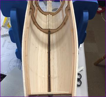
Pretty much the last job of the month, which I have to admit I had been putting off for a few days, was the removal of the temporary formers F2 and F3. Before tackling this I had brushed the outside of the planking with diluted PVA and allowed it to dry. This is something I often do anyway on the basis that any slight swelling of the planks will help close the gaps and the dried PVA helps bind the surface together when sanding. This time though there was another objective - I was hoping that dampening the wood might ease some of the stresses I'd created by the forceful pulling in of the nose.
While applying the planking, I'd tried not to glue the planks to F2 and F3 but of course there's still a bit of glue gets onto the formers from the joints between the planks. In the event the formers broke out cleanly enough. There was no discernable movement at the F3 station and only a millimeter or so at F2. So, I'm very happy with the outcome and will shortly be passing the fuselage to a more brush-competent clubmate for glassing of the cockpit interior.
February 2020 While the fuselage was away for its internals to be glassed, I made a start on the tailplane. The full size example on which I shall be basing the colour scheme has been fitted with a fixed tailplane and conventional elevator. However, there is no doubt that the original all-moving tail is far more elegant so that is what I'm planning to use. Besides, it's what's drawn on the plan and I've paid good money for the laser cut parts!
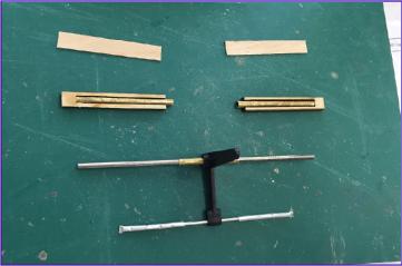
Having bought a suitably sized commercial horn, it was then a question of ferreting around in the bits boxes to find a suitable permutation of tubes and rods to assemble the linkage. Then. with the help of the pre-cut parts, the tailplane halves went together pretty quickly.
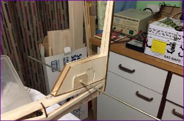
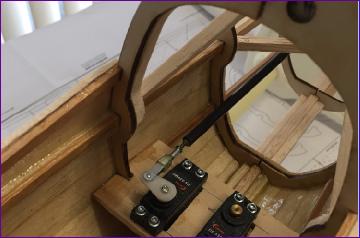
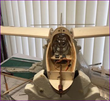
By now the fuselage was back, with the inside of the cockpit beautifully glass skinned - thanks Peter! Mounting the tailplane pivot in the fin is one of those jobs where a bit of thought and extra care is needed if everything is to line up properly - and you are to avoid gumming up the works with stray cyano. I elected to build the fin in situ, and used a long length of piano wire to help with sighting things up.
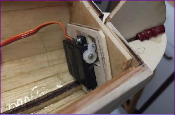
A 6mm carbon tube was used for the elevator pushrod and a servo tray fitted at the rear of the cockpit aperture.
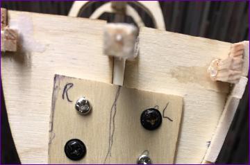
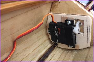
I had originally provisioned another Corona DS 339MG servo (as used for the elevator and rudder) for the tow release but, surveying that nice empty cockpit to work out where and how to mount it, I started thinking about more radical options and came up with this arrangement, using one of the DS 239MG wing servos.
It works well, but with hindsight, it would have been possible to mount the servo 5 or 6mm lower which would have practically eliminated the kink in the pushrod.
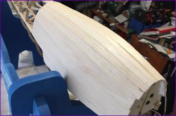
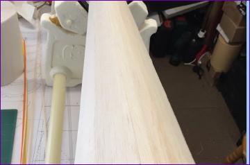
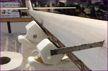
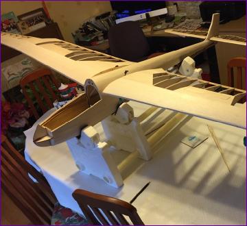
After all that mental exertion working out linkages etc., it was almost a relief to get back to some straightforward balsa bashing, sheeting in the top of the fuselage. This is shown as 0.8mm ply on the plans but, as with the nose section, I opted for balsa. 3/32in on this occasion.
Unfortunately the wood that I had showed absolutely no interest in rolling around the rather tight radius at the rear end so, although it's only a single curvature section, it had to be planked.
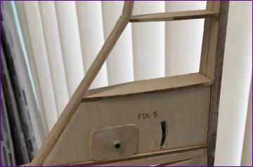
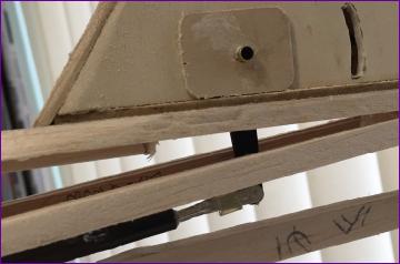
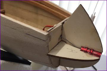
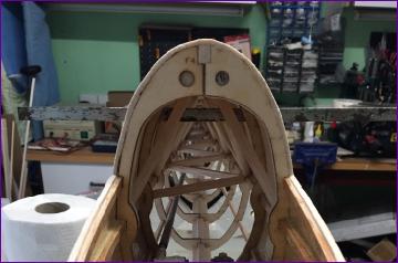
With the turtle deck in place, the fin was now sheeted (1.5mm balsa) and its leading edge fitted. A minor cockup here - as you can see in the picture, I'd carefully positioned the hole for the AMT pivot but forgotten to cut the slot for the actuating rod to pass through. This was relatively easy to remedy later, after a bit of careful measuring.
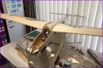
By now though, I was realising that the time was looming when I'd have to tackle probably the trickiest bit of this build - the wing to fuselage joint.
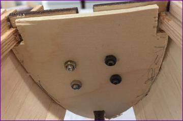
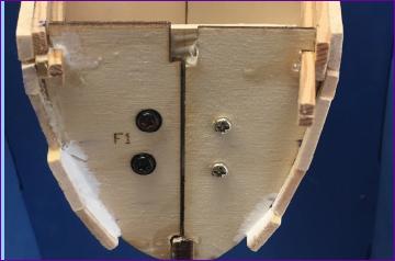
After yet more careful measuring, I gingerly opened up a slot just big enough to take a wing joiner bar. Both the shots below were taken with the tailplane fitted, so you'll appreciate how pleased I was to find that it was totally obscured by the wing joiner when viewed from the front! So far, so good.
Next, the holes in the fuselage were carefully eased out to take the brass joiner box, then the process repeated for the incidence wire.
So, as an exceptionally wet and windy February drew to a close, the model could at last be assembled, and another bit of head scratching and improvisation loomed as I contemplated how to fabricate the fairings.
Hopefully next month, I'll be able to tell you how it worked out!