March 2020 (Click here to return to part 2) By the start of March, it was clear that the Covid 19 pandemic was really getting going and, sure enough, by the middle of the month serious movement restrictions were in place in the UK, pretty much confining us retired folk to home. Maybe that is why there is quite a bit of progress to report on the Petrel this month!
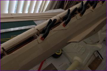
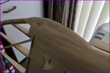
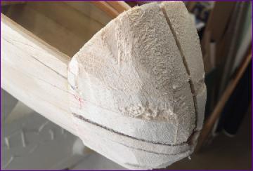
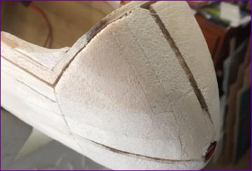
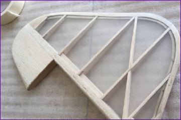
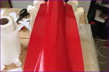
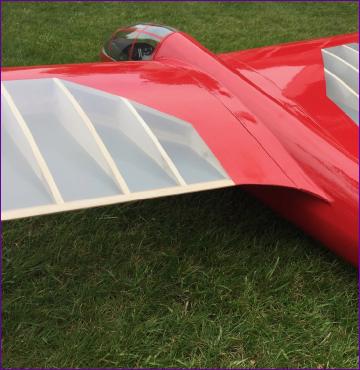
The first job was to carry on sorting out those tricky wing fairings. Being a retired vehicle finisher, the designer is a dab hand when it comes to the use of car body filler, so the plan simply says to fill in the gap between the fairing facing and the fuselage with rough cut balsa blocks, then finish the whole thing with filler. I have a pretty good idea how that approach would turn out in my hands so instead set about building up enough supporting structure to sheet in the area with 1/16in balsa.
The 1/8in balsa fairing ribs are not shown on the plan but are needed to support the sheeting. Needless to say, there were innumerable trial fittings of the wings to ensure that the 1/16in sheeting would align with the profile of the wing. There were almost as many trial fittings required afterwards to make sure that, once the ply facing ribs were added, a reasonable 'shut line' would be achieved between wing and fairing. Eventually patience was rewarded with a pleasingly good fit.
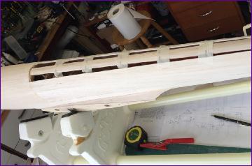
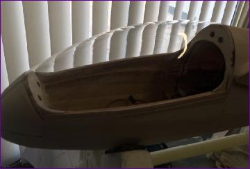
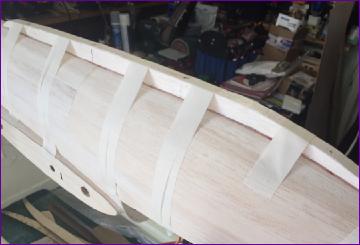
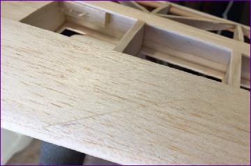
After the stress of the fairings, it was a welcome relief to set about planking in the underside of the fuselage. Again I used 3/32in balsa for this rather than the specified 0.8mm ply.
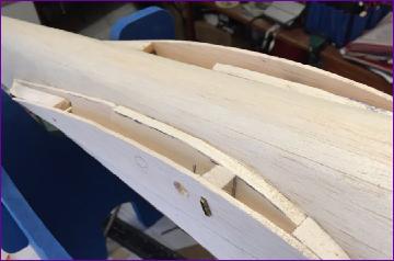
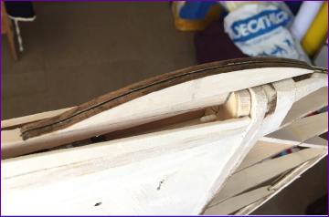
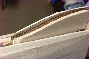
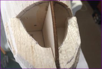
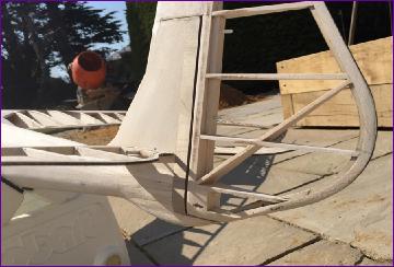
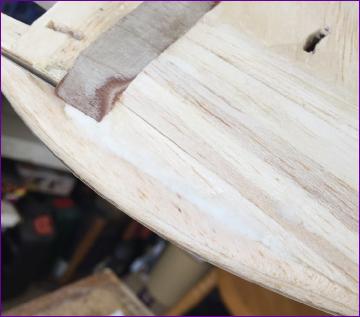
Fortunately I'd remembered to install a couple of guide tubes for the closed loop wires before doing the planking - even though I didn't remember to photograph them! However, having got to this stage, some decisions had to be made about the tailskid. This is shown as laminated from a core of 0.8mm ply with 3mm balsa either side. The skid is then just glued onto the fuselage skin. In my case of course, the skin is 3/32in balsa rather than ply so I was a bit concerned about this arrangement. In the end I opted to slim the skid down to 6mm total width, then apply another balsa lamination on each side, extending down either side of the keel.
As well as hopefully securing the skid a bit better, this approach also had the benefit of enabling the skid to be blended into the rear fuselage with minimal use of filler.
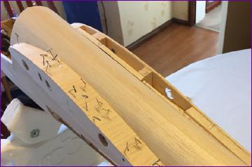
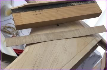
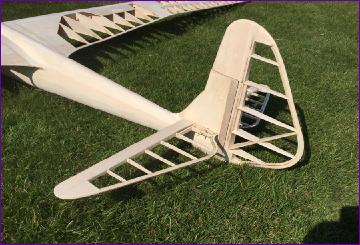
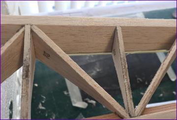
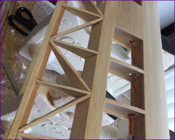
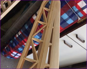
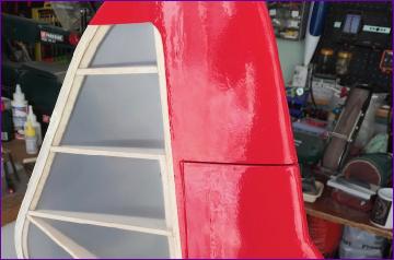
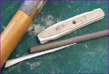
While at the back end of the model, it seemed a good idea to sort out the shrouds for the rudder hinges. These are from 1/64" ply, let into the fin's balsa skin with the aid of the custom tool shown below (thanks Martin!)
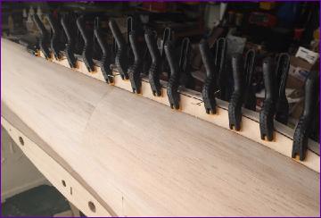
Turning attention back towards the other end of the fuselage, the spruce canopy rails were laminated with 3mm balsa on the outside, then the front and rear canopy formers were fitted, supported by balsa corner webs.
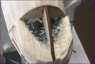
At this point the model was assembled for a rough balance check in order to get an idea of how much lead to build into the noseblock. Based on this, some 5oz of lead shot were built into the lower half of the nose. . .
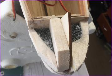
.. . followed by another 3-4oz in the top half, taking care to ensure that the tow release pushrod was kept clear.
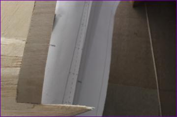
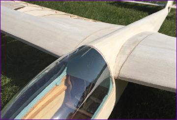
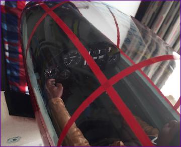
The noseblock was then roughly shaped using the canopy frame as a guide but, before it could be finally sanded to shape, the actual canopy was trimmed so that it could be dry fitted to check that the shapes matched.
At this point it seemed just as well to go ahead and paint the canopy frame and glue the canopy to it. The instrument binnacle has also been built but the instrument panel will be left until a pilot has been obtained.
As the list of remaining construction jobs finally began to shrink, the aileron linkages were the next one to cross off.
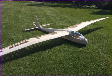
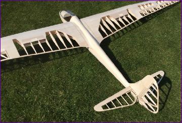
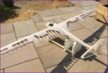
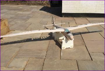
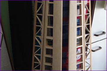
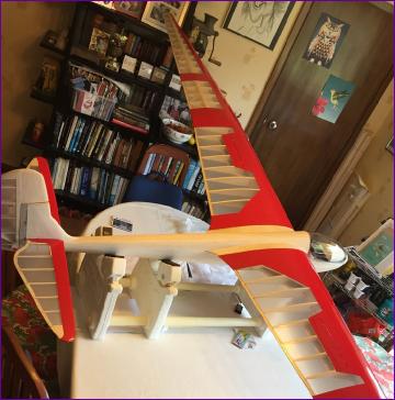
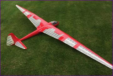
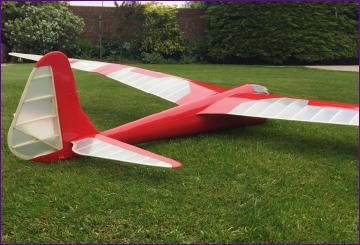
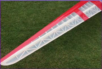
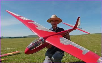
At this point, I took advantage of some sunny weather (and a reasonably newly mown lawn!) to put the bare model together one more time for a few photos.
The last job on the list was the main skid. Two 2mm ply side plates are supplied in the short kit, to be applied to a 12mm balsa core. I made the core up from two laminations of 6mm balsa and fitted it to the underside of the fuselage. As with the tailskid, I was concerned about simply gluing it to the balsa skin so reinforced it with a few short lengths of carbon fibre rod, inserted through the skid and into the fuselage keel. Once this was done, the ply side plates were added, followed by a ply facing to the underside of the skid.
So, with the construction phase nominally complete, that's it for March. There's a fair bit of tidying up of the airframe (and workshop!) to do before covering gets underway.
The quality of the short kit has generally been very good. However, with hindsight, I would have saved myself time by cutting my own ribs for the ailerons. The supplied set have absolutely no trimming margin and most of them needed thin balsa shims added on the top or bottom - and sometimes both. I now have a set of ailerons which are satisfactory in shape but the charring from the laser cutting process poses a bit of a problem since the covering will be transparent. Hopefully next month, I'll have solved this little issue, one way or another.
Meanwhile keep safe from this wretched virus!
April 2020 Well, after much cogitation, the charred edges of the aileron ribs were disguised with a dab of paint. The result is far from perfect but much improved from what it was. After a bit more sanding and general fettling, the fit of the ailerons is also now acceptable.
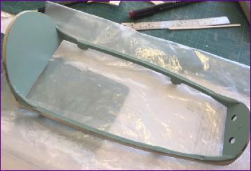
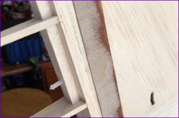
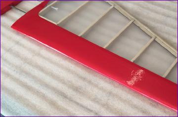
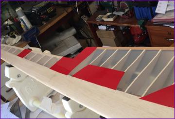
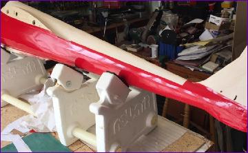
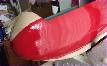
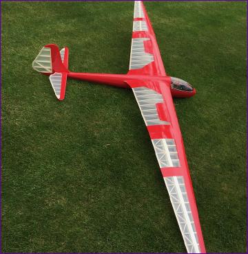
After so much effort building an airframe like this, people often make remarks along the lines of 'It's a shame to cover it all up'. Although the open structure will still be visible through the clear covering, it is true that the sheeted areas will be well hidden away behind solid red film. So, the next batch of pictures are pure vanity shots - they'll not help any other builders but will give me something to look back on to remind me that I did a half decent job of some aspects of the build at least. Mind you, I have included a couple of shots showing that I did have to resort to the use of filler in some places!
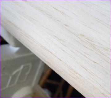
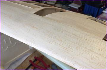
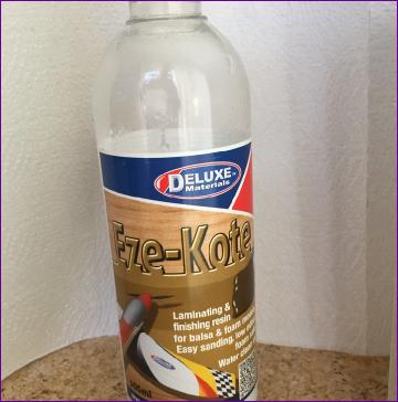
Before covering, it was time for a bit of an experiment. A fellow modeller had recommended this product as a pre-covering treatment, saying that it hardened the surface of the balsa, giving it a bit of ding resistance.
Now generally, apart from ensuring it is dust-free, I don't pre-treat balsa before covering. Apart from the risk of affecting the adhesive on the film, I was concerned about the potential for messing up the sole plate of the iron and also, if it seals the wood, the potential for trapped air bubbles.
However, the advice came from a trusted source and the finish that this modeller regularly achieves is recommendation enough in itself. So, not withstanding my phobia for all things brush-related, I decided to give it a go.
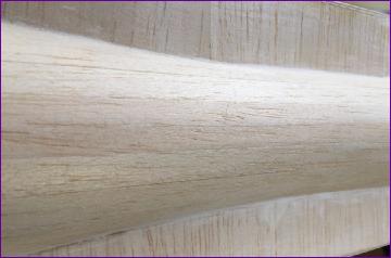
For a gentle start, I tackled the rudder and tailplanes first and, I must say, I'm impressed! After a coat of the magic liquid, the fuselage planking sanded back really well - it seemed much easier to sand down the high spots now that the surface was a bit harder. As for it affecting the covering process, I encountered no problems with the adhesive and have to admit that, with the balsa being harder, it suffered far less bruising from the edges of the iron.
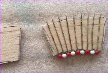
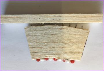
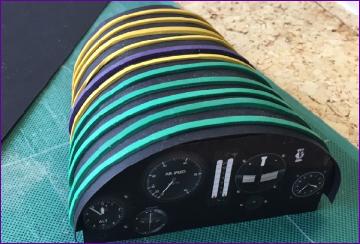
The clear covering was applied to the wings next. This covers most of the open structure but has to extend onto the sheeted areas in order to anchor it. As a result the red covering unavoidably overlaps somewhat with the clear - a definite recipe for trapped air bubbles! The only way I know of to avoid this problem is to perforate the first layer of film in the areas of overlap, enabling any trapped air to dissipate through the porous wood. There is a rather evil looking tool (Google 'Woodpecker perforator') sold specifically for this purpose, but I decided to have a go at making my own.
First, a few pins were positioned on a scrap of 3mm balsa with the aid of double sided tape.
Then a second piece of balsa was glued in place and the whole lot clamped in the vice overnight.
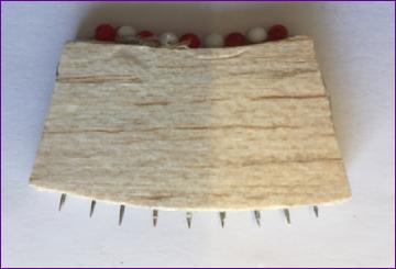
Finally, a scrap piece of 6mm square balsa serves as a safety guard.
All in all, the work of a few minutes and, in spite of its crude simplicity, it is very easy to use and works magnificently!
So, with the overlap areas duly perforated, the red film was applied, starting with the areas aft of the spar. The spoilers were covered and fitted, offcuts from the canopy being used as spacers while the hinges were glued in.
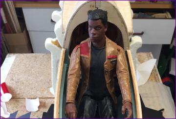
When I was busily packing lead shot into the noseblock last month, I hadn't got a suitable pilot figure to hand.
However, I have now been given the fine fellow pictured a little later. Although arguably slightly undersize, he makes up for this in weight, coming in at a portly 6.5oz. A balance check with pilot on board before covering had shown the model to be nose heavy so, before going prospecting in the noseblock for lead shot, I assembled the model for another balance check to see how much the cg had shifted as a result of covering the flying surfaces.
I was pleasantly surprised to find that the cg had shifted back pretty much to the plan position. Although there is still detailed work to be done in the cockpit, I'm going to assume that covering the fuselage will compensate for this so will leave the noseweight in place.
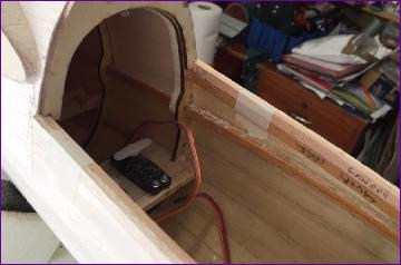
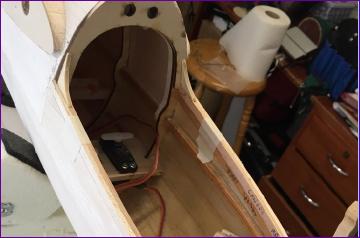
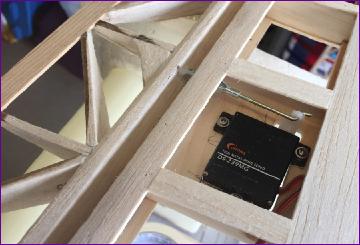
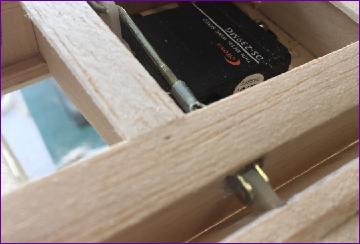
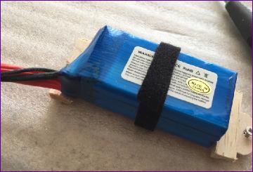
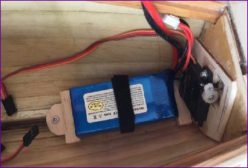
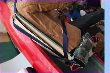
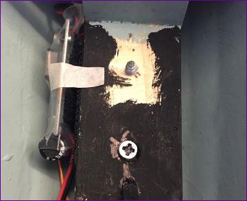
Heartened by the cg test, I opted to press ahead with some of the cockpit fitting out before covering the fuselage. First up was the issue of battery stowage. Initially, the model will be fitted with a 3s x 1300mah LiPo battery but I didn't want to design any permanent fixtures around this particular battery in case it might get swapped for something else in the future. The only bit of structure that looked suitable for a screw-in fixture was the keel so a simple tray was fabricated, the battery located by two balsa stops and a Velcro strap. The assembly locates under the tow release servo and is secured by a single screw into the keel. Hopefully, if a battery change is needed, it will involve nothing more than making a new tray.
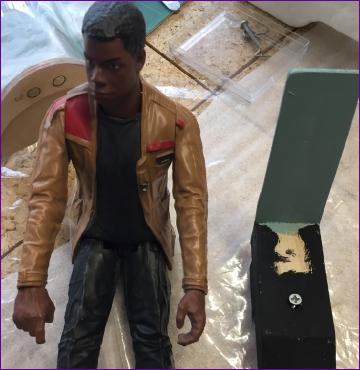
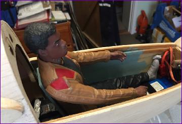
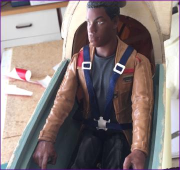
So, here's the likely lad mentioned earlier. To raise him to a sensible height, a seat was fashioned out of balsa wood. This involved surprisingly little work since for once, the scrap box yielded a lump of balsa block of suitable width and length. It was even shaped to go under his knees. All I had to do was cut a groove in the underside so that the seat would sit over the keel and angle the back of the block to add the 3mm balsa seat back.
If making the seat was relatively painless for me, I fear the pilot may not feel the same about the means of securing him to it. I'll spare you the details, but I have to admit to feeling a little squeamish when drilling the necessary hole!
Once again, as with the battery tray, the assembly is screwed to the keel.
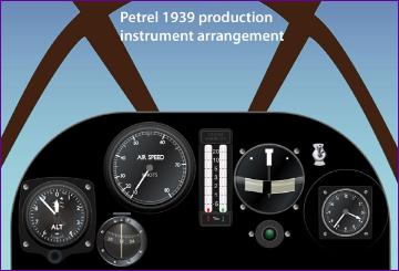
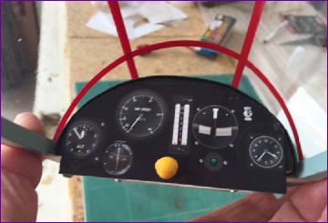
For the instrument panel and binnacle, I took the simple, paint-free, approach. The panel was printed out from the image below, found on the SSUK website, then the binnacle was wrapped in matt black card.
The last job of the month was to make a harness. This is just 1/4in ribbon, stitched together at the buckle position, with the ends of the various straps secured to the seat block with drawing pins.
In keeping with this high tech approach, the release buckle and sliders are cut from thin silver card.
So, perhaps when folk ask what new crafts did I try during the lockdown, I can claim to have practised découpage!
Well, that's about it for another month. Unless I get diverted onto other things, the Petrel will definitely be flight-ready at some point in May. When I might actually get to fly it is of course another matter entirely.
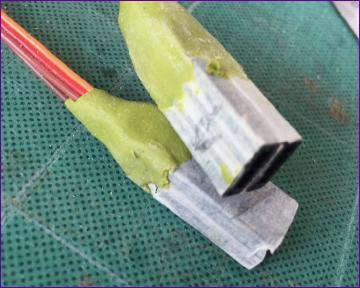
May 2020 The first job I tackled was the wiring connection to the wings. The ends of two pairs of extension leads were bonded together, with a view to fixing them in the fuselage wing roots, the leads from the wings would be left free.
Then an odd snag arose. Although the leads had been checked for compatibility beforehand, once the sockets were fitted in the fuselage, I could no longer mate the connectors. Fortunately this was only a dry fit, so the leads were removed from the fuselage - and Hey Presto! they once again mated perfectly. Totally baffled, I repeated the whole exercise. Sure enough, the extensions mate fine on the bench but not when fitted to the model.
After a long cup of tea and some serious thinking, the mystery was solved. It seems that with these particular (cheap!) extension leads, the inserts are quite a loose fit in their plastic housings. When mounted in the model, the weight of the lead hanging down in the fuselage is enough to pull the inserts slightly out of line and so prevent insertion of the plug.
Clearly some form of support for the leads was needed. Fitting anything inside the fuselage was obviously going to be difficult, if not impossible. Then I suddenly remembered that years ago I'd read about a wonder product called Sugru. I'd bought a pack and never used it. Fortunately it was stored in the fridge so was rather easier to find than it otherwise might have been!
The pack was well past its 'use by' date but there was nothing to lose by having go. I opened one of the sachets and set about moulding some cable boots. You can see the result in the picture. They don't look too pretty but they do the job and the connectors are now glued into the fuselage and have given no further trouble.
So, after that little diversion, it was back to the ironing:
Installing the remainder of the wiring proved trickier than anticipated. I velcro'd the uBEC to the side of the pilot's seat but then couldn't get the seat in place. As you can see from the picture below, I was trying to 'lose' some surplus wire in the same area, which wasn't helping. A bit of a re-think saw most of the extra wire pushed back under the servos.
Even then, the seat was still reluctant to locate (the pilot has to be screwed and strapped to his seat first so it's impossible to see what's going on. Eventually though, the retaining screw did bite, although I still don't really know what the issue was.
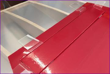
I normally don't look forward to jobs such as lining the canopy (with red vinyl) but, after such a struggle with the pilot's seat, it came as a pleasant change.
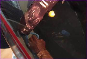
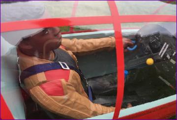
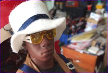
The pilot has no functioning elbow joint so can't grasp the control column. He is actually a Star Wars character called Finn, who is more used to wielding a weapon of some sort rather than flying. In fact his right hand has a permanently cocked trigger finger! His left hand though looked like it could hold something and a quick bit of research showed that there is a blue pull handle for operating the spoilers in the appropriate position. So bit of wire was covered in blue heatshrink before being bent into shape. While I was about it, a second sachet of Sugru was used to make a tow release knob. Since the whole sachet starts curing the moment it is opened, I rolled up three different sized yellow spheres, eventually settling on the smallest one.
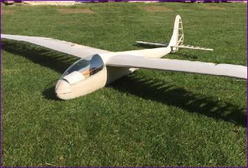
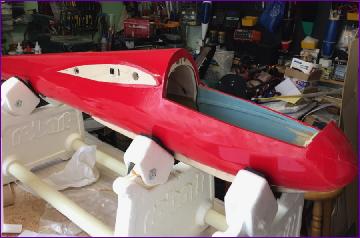
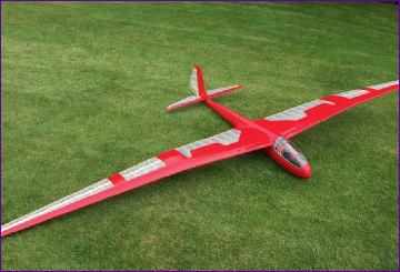
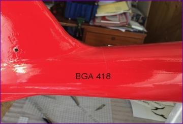
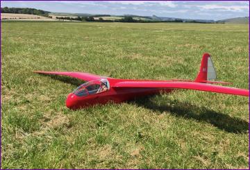
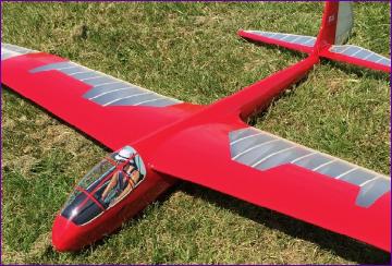
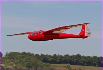
So, with the covering finished, wiring sorted and cockpit fitted out, it was out onto the gras for another photoshoot.
The full size Petrel carries very little in the way of markings. My model is only loosely based on the full size so I didn't seek to replicate it exactly.
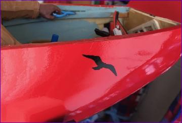
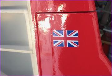
The black vinyl decals were cut for me by a fellow modeller but I then decided that I'd like to add the Union Flag logo on the fin. I printed this out onto clear decal paper then stuck it to a piece of white vinyl before cutting it out and sticking it onto the model.
The last of the finishing touches was to equip Finn for the remarkably sunny springtime we are enjoying in the UK. Actually 'enjoying' is perhaps not the best term since at this stage we were in lockdown due to the Covid 19 pandemic.
However, within a few days of completing the model, some slight easing of the lockdown rules meant that flying was now permitted. So, after a last minute panic about decalage angles, which resulted in a significant re-trim of the all-moving tail and a corresponding enlargement of the slot in the fin, the model was in the car and on the way.
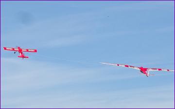
I've only ever conducted maiden flights of gliders off the slope. However, with no sloping opportunities on the horizon, I took the model along to our splendid flat field site with a view to trying to fly it from an aertow launch. Chris Williams the designer was there and gave the model a good dose of looking at, then recommended a hand launch test flight over the 18in high crop surrounding the field. This went well so the Petrel was hitched onto the line and off we went.
The Petrel went up the line beautifully. I didn't go very high and there was no lift about so the flight was brief. However, it handled pleasantly and seemed very promising. A second flight enabled me to dial in a little spoiler to elevator mixing to help keep the landing approaches smooth.
I look forward to having some longer flights off the slope to fine tune the setup and explore the model's capability further.
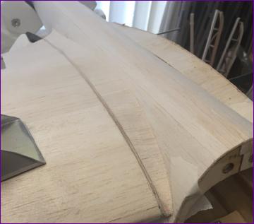
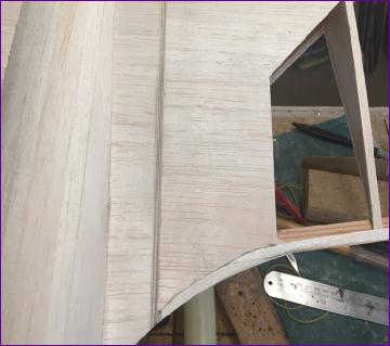
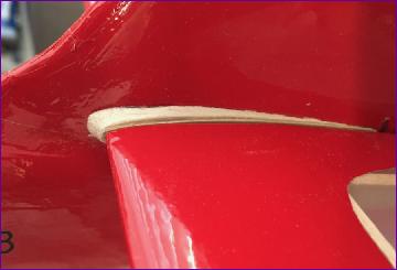
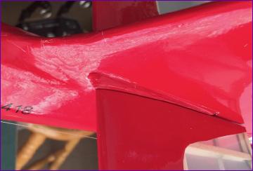
Meanwhile, now that the trim position of the all-moving tail had been established, there is one more bit of building to be done - the tailplane root fairings on the fin.
The fairings were made from 3/16in balsa, with a 1/32in ply facing rib. Most of the balsa is sanded away to match the contour of the fin.
Using the neutralised tailplane as a guide, the fairings were then glued to the fin and a smear of filler applied to the joints.
Finally (and tediously!) the fairings were film covered.
I'll close the diary at this point but, as always, will add more pictures (or flying tales!) as and when they become available.