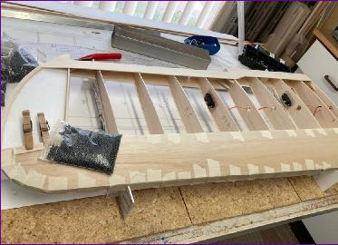
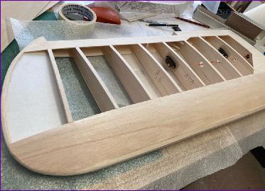
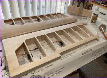
The estimate of a couple of weeks for completion of the wings proved to be about right. A fair bit of this was spent on the less-than-photogenic tasks of closing off the control surfaces, cutting hinge slots and sorting out control linkage arrangements. A couple of cradles were made from foam board to support the wing while the upper leading edge sheeting was added then, once the cap strips and leading edges had been added, the wings were beginning to take on a finished appearance, albeit still in need of a fair bit of sanding.
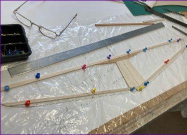
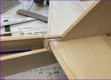
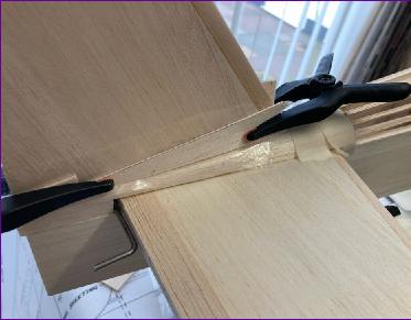
By this time it was clear that I was running out of 1/16in sheet balsa. We no longer have any local model shops and I was not yet ready to place another substantial order for wood so my normal approach of skinning the tail surfaces with 1/16in balsa was going to have to change. In some ways this probably wasn’t a bad thing because the tail surfaces can be subjected to some extra stress when towing, particularly when a wayward glider starts trying to use the towline as a cheese wire. A framework of 1/8in balsa was drawn up, incorporating a bit of spruce to reinforce the centre section. This spruce brace is inset from the trailing edge so that it doesn’t get in the way of cutting hinge slots.
This framework was glued together over a skin of 3/32in balsa, then the top skin was added followed by a leading edge cap strip. It was at this stage that I remembered that I had intended to move the elevator hinge line rearwards about half an inch, partly to reduce the size of the elevators and partly to reduce the offset between the elevator and rudder hinge lines to make it easier to fit bracing wires to fend off the aforementioned cheese cutter towline. So, a substantial strip of 3/8in balsa was added to the trailing edge, to make up for this oversight. Plenty of room for those hinge slots now!
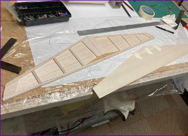
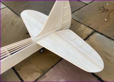
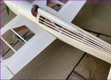
A similar approach was taken to the fin, but this time a 5mm internal framework was used, with 5mm sq spruce Incorporated as false leading and trailing edges, the former left slightly long to key into the top of the tailplane, the latter extending down into the fuselage. Elevators and rudder were simply made from a core of 3/32in balsa with stiffening ‘ribs’ on either side.
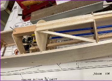
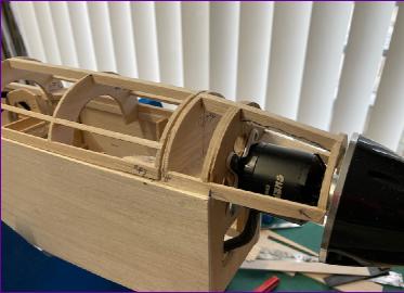
With the tail surfaces dry-fitted, a start was made on the rear turtle deck. This is an open stringer work on the original and I want to keep this feature in my enlarged version. However, once again, the intended towing duties gave pause for thought. I had made provision to mount the tow release mechanism itself between two ply formers but was still concerned whether the stringers would be enough to stop the whole lot being pulled backwards under a snatch load from the towline. So a couple of diagonal braces were added. All this is dry fitted in this photograph because the 6mm square spine piece cannot be fitted until the fin is in position - and that means that the tailplane has to be fitted first.
So, after lots of checking for alignment and general fettling, the tail surfaces were glued in place. I did give them a first sanding beforehand, and was quite pleased that, for once, I remembered to leave the lower section of the fin leading edge square, in anticipation of fitting a small fin strake later.
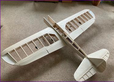
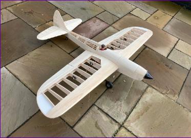
That’s about it for another month so once again it’s time to fit all the various bits together, just to see how it is all taking shape. So, will it be finished by Christmas? Place your bets. . . .
December 2021
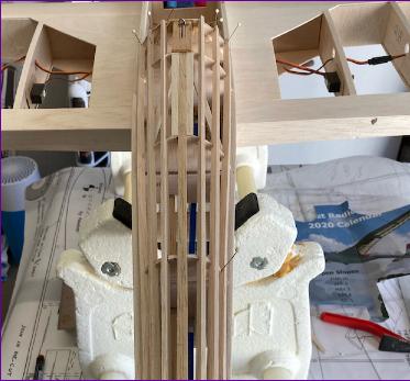
So the general plan now is to start at the back and work forwards. The original Spectre has a stringered turtle deck which is a feature I was keen to retain, so this was the first job.
The stringers are nominally 1/4” x 1/8” to try to make them a little less delicate than they look. Whilst fitting them is not complicated, I always find that a lot of care is needed to get them straight and any suggestion of waviness can easily spoil the look.
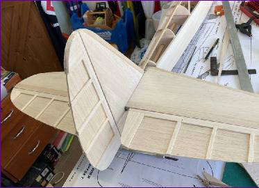
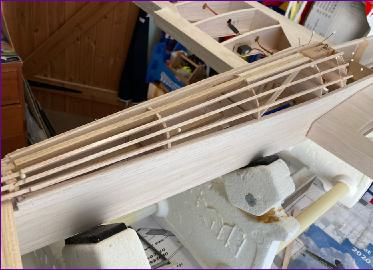
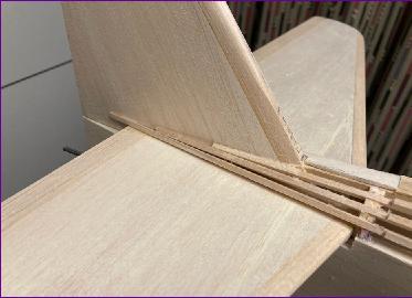
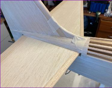
I opted to take some of the stringers all the way back towards the stern post, sanding a ‘step’ into them just ahead of the tailplane leading edge, in anticipation of sheeting the section between the fin and tailplane.
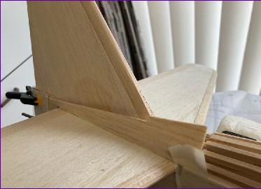
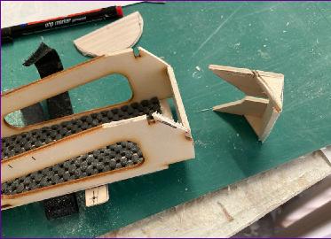
These 1/16” balsa fillets were cut to size, glued to the lowest stringer and tailplane then, when the glue had dried, rolled over and glued to the remaining stringers and the fin. All a bit of a fiddle but I think the result is neater than I would have managed with block balsa fillets. A small fin strake was then added to complete the tail end.
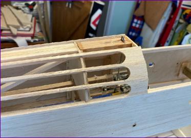
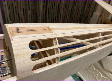
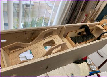
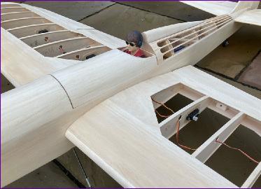
Attention then turned to the other end of the stringers where another little fiddly job awaited: fitting scalloped infill pieces between the stringers. Once sanded back, they do neaten the whole thing off. The space above the top stringers was also filled in to provide a firm base for the head rest, and recesses drilled for retaining magnets. (The headrest is to be removed for towing duties).
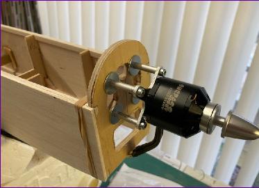
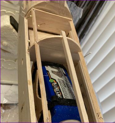
The time had now come where I could no longer put off the decisions about battery stowage. Another trial balance suggested that the model might still be tail heavy even with a 4000mah 6s battery tight up behind the firewall.
A set of stand-offs was therefore made (from the carefully archived wreckage of a long-departed helicopter!) just in case the motor had to be re-located forwards. Having now got a means of adjustment of motor position, I felt confident enough to glue the firewall in place.
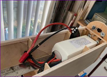
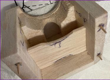
Then at last a battery box was made (this time using unused ply parts from the recent Mustang build).
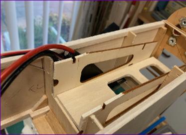
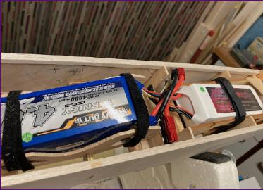
Those who have been following the plot carefully will remember that the hope is to be able to fit a second battery (wired in parallel with the first) when undertaking towing duties. So, a second battery box was needed to locate over the cg. It was at this point that I started to get concerned about just where this cg should be.
The Spectre plan shows the cg at 21% of the root chord. The taper on the wing is almost symmetrical, so this did seem rather well forwards. Was this, I wondered, a characteristic of control line models or maybe it was because the flat plate flaps couldn’t really be regarded as part of the wing? Recalling that I had pinched the wing section from the Mustang and that that model flies very nicely, I dug the Mustang plan out of the archive and found that the cg on that model is at 30% of root chord. Applying that to the Spectre puts the cg 38mm further back than on the Spectre plan. Allowing for the slight forward sweep of the spectre wing, I'm tempted to start at about 25% of root chord, i.e. about 18mm behind the marked position.
Yet another trial balance indicated that, depending on how much the covering moved the cg rearward, I might just get away without those motor stand-offs after all. Anyway, for now, I at least had a better idea of where this auxiliary battery should be positioned. The rather shapely curve cutaway in the sides of the box is to allow access to the nylon wing retaining bolts.
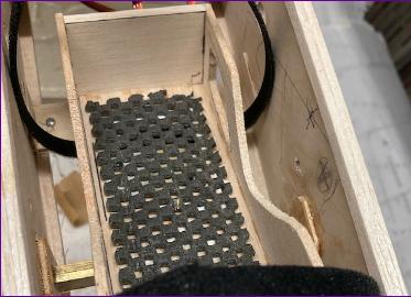
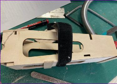
Both battery boxes have non-slip matting on the floor and are secured by small screws into hardwood blocks in the fuselage. Velcro straps retain the batteries in the trays.
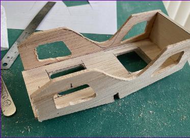
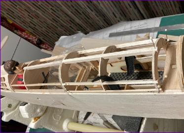
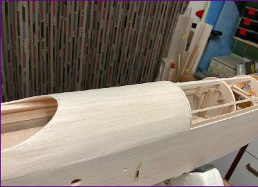
With the battery boxes sorted, it was now time for the access hatch arrangements to be finalised. My initial idea had been to have the whole upper section from the cockpit to the firewall removable as a single hatch. However I decided it might be more manageable to have two hatches so that only the forward one had to be removed for normal sport flying, the rearward hatch only coming off when the second battery had to be fitted for aerotowing.
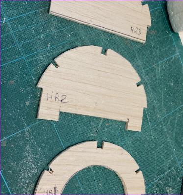
A start was made on the rearward hatch, by cutting out three formers from 3mm balsa. Once the framework of the hatch was done it seemed a good idea to defer sheeting it in until the forward hatch was built and the retaining catches, magnets or whatever had been sorted out.
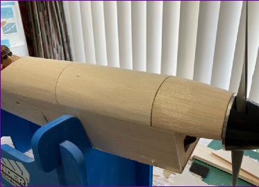
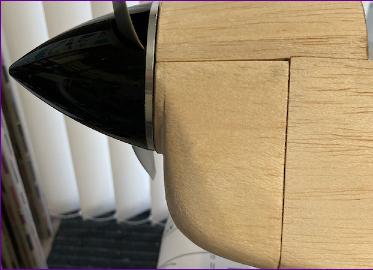
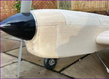
Looking at the front hatch, it was clear that the transition between the simple, single-curvature upper decks and the compound curve of the nose would have to start well behind the firewall if the fuselage was to blend smoothly into the spinner. I had also been looking ahead to the cowl and wondering whether to go for a full i.c.-style cowl or to make the upper section fixed and just have a removable ‘chin’ cowl. I went for the latter approach because it meant that I could plank the upper fixed portion of the nose and, by extending the planking back an inch or so behind the firewall, avoid the need to build in any significant compound curves into the hatch.
So pleased was I by this decision that it was a while before it dawned on me that this extended nose planking would mean that the forward battery tray could no longer be dropped vertically into place. It therefore underwent some rather brutal surgery so that it could still be manoeuvred into position.
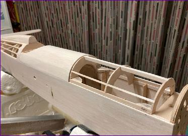
The front hatch was now framed up, and decisions made on how the hatches were to be retained - the rear one by sliding it backwards into position, the front one by four pairs of magnets. The rear hatch was sheeted in then another assembly and cg check was carried out to decide finally whether to use any standoffs to move the motor forwards.
Eventually the decision was made to do without the standoffs so a start was made on the framework for the upper nose planking.
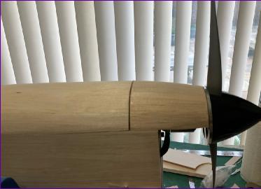
Planking was done with 1/8in balsa. After a light sanding, this was coated with dilute PVA. This process brushes balsa dust into any gaps, swells the wood and glues the planks together. With any luck, the planking then can be sanded smooth without the need for any filler.
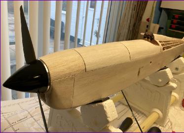
Finally, once all the mating faces of the hatches and apertures had been trued up, they were faced with 1/64 ply and the whole upper deck was attacked with the sanding blocks once again to blend all the components together.
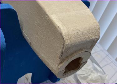
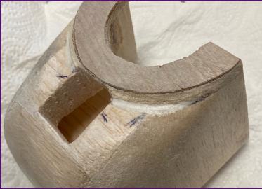
The last construction job was the chin cowl itself. This was a relatively simple construction of block balsa, the only issue being just how hard to attack it with the sanding block to round it off, without running the risk of sanding into fresh air at the corners.
Talking of fresh air, an air intake was opened up in the chin and an internal baffle fitted to direct some air up through the motor before it continues aft, past the ESC and batteries and out through the cockpit aperture.
At the moment the cowl locates on four cocktail sticks and is held in place by friction. I’ll defer any consideration of a more positive fixing until after covering - there’s always the option of just ironing a strip of covering over the join, since I don’t envisage cowl removal being a frequent job.
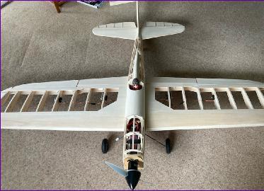
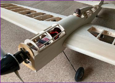
All the various components were then subjected to the usual rounds of filling and sanding before being given a couple of coats of Eze-Kote to toughen up the balsa before covering.
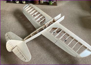
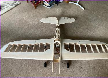
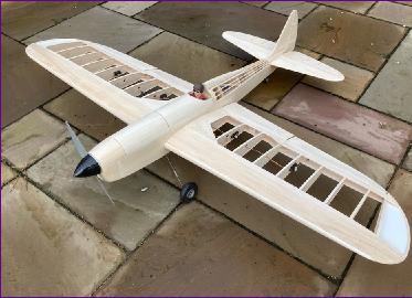
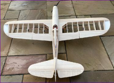
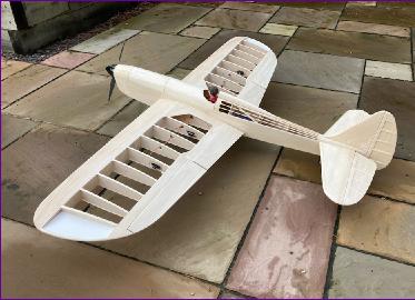
This point was reached on New Year’s Eve so it seemed appropriate to end this diary entry with one last naked photo shoot, and look to 2022 to start the covering process.