Spectre Project Diary -Part 1
I know that many modellers have a long list of ‘must build’ aircraft and a stash of unstarted kits in their lofts so their ‘what to build next’ challenge is simply one of choice. My situation is different. This year’s flight log (2021) lists more than 40 models (not counting the little indoor ones), all flight-ready and competing for car space on each flying outing. So, when contemplating a new build, the chosen subject either has to bring something completely new to the fleet or represent such an improvement on an existing model that I can invoke my long standing (but less than fully successful) ‘one in, one out’ policy in order to avoid exacerbating my ever more desperate space and storage crisis.
So it was, as the Mustang build drew to a conclusion in early summer 2021, that the familiar question once more raised its head - what to do for a winter build? Over the last couple of years I’ve been lucky enough to fly with a group of enthusiastic glider flyers who hold regular aerotowing sessions. Although I do have a model available which has some towing capability, it has its limitations (and isn’t really mine!) so doesn’t come out very often. The fact is that, when it comes to competing with those 40+ other models for a space in the car, a dedicated tug isn’t going to make the cut unless I’m sure it’s going to be needed. So I started musing on what I might build that could justify its place in the fleet in its own right and also be pressed into service as a glider tug when the need arose.
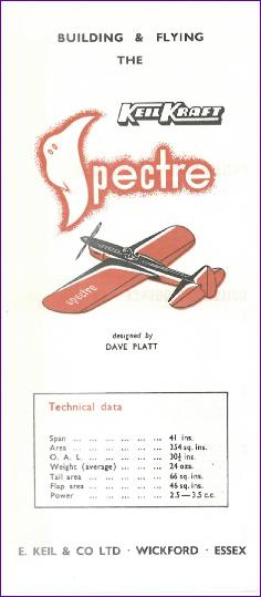
I’d already decided that, following the Mustang, it was time for a non-scale project so attention naturally turned to a sport aerobatic model. The competition here is considerable - I already have the Capiche, Astrohog, Kwik-Fli and Aeromaster. As I type that list, I realise now that the Capiche, published in 2000 is the most modern design of the lot. So arguably, in the quest for something different, maybe I should have dragged myself into the 21st century and gone for an up-to-the-minute modern design. However I went the other way, gave in to nostalgia, and found myself looking at the control line models that I had lusted after in my schooldays. It didn’t take long to whittle down the shortlist to a choice between the Mercury Crusader and the Keil Kraft Spectre. Both are classic designs of the 1950s and in the end the Spectre won the day.
The plans were downloaded from Outerzone - an invaluable resource. Although to me as a schoolboy, the Spectre seemed like a big model, from my current perspective at 41in span, it is rather small, so the first question was how much to scale it up? For towing gliders up to 1/4 scale, 6s LiPo power seems to do the trick. However the battery does take a bit of a pounding, with the motor at full chat throughout the climb out. I run 6s x 4000mah batteries in my Avanti so it would make sense to be able to use the same size packs in the Spectre, ideally with the option to fit two of them in parallel for towing duties.
Looking at the existing fleet for size comparisons, my eye was drawn to the Astrohog. At 72in wingspan, this model (admittedly built very light) comes in at an all-up weight of just 5lb 8oz, including a 5s x 3700mah battery. I’ve since stopped using 5s batteries and the Hog still performs very nicely on 4s. So I reckon that a somewhat more sturdily built Spectre of similar size could weigh 6 - 6.5lb and should fly very nicely on a 6s pack. So I had the plan printed out, scaled up by a factor of 1.75. This gives me the option of either a 72in or 73.5in wingspan, depending on which of the two wing panels I build from - unlike the C/L version, I want both wings of my Spectre to be the same size!
As well as equalising the two wing panels there were a few other obvious C/L features do dispense with such as the counterweight in the right hand wing and the inbuilt rudder offset, all of these of course being aimed at maintaining tension on the control lines. However, as I studied the plans over the next week or so, I built up a surprisingly long list of other modifications to be made:
Flaps/Ailerons The flaps on a control line model deflect in the opposite direction to the elevators in order to tighten looping manoeuvres. I of course need to re-purpose them as ailerons but, as drawn, they have a very deep chord at the inboard end and taper strongly towards the tip. To be effective as ailerons this really the opposite of what is needed. After some deliberation, I opted to keep the inboard portion as flaps and move the hinge line forward on the outer (aileron) portion. Also, the flaps are simple flat plates hinged onto the trailing edge of the wing. I know this approach is still taken on some fun fly models but I felt uncomfortable about using it on this one and decided on the more conventional approach of building the ailerons and flaps into the wing. This led on to the next question:
Wing Section The Spectre has a fully symmetrical, very thick wing section, no doubt partly to try to prevent excessive speed building up during the downlines of looping manoeuvres. Having just done the first few flights with the Mustang and been very happy with the way it handled, I opted for the devil I knew, traced the section from the Mustang plan and scaled it up to match the root and tip chords of the Spectre, in the hope that the intermediate ribs could be cut out using the sandwich method.
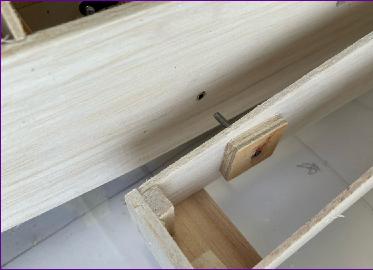
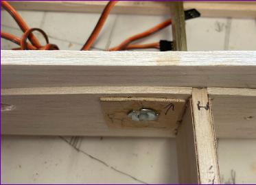
Wing Fixing The Spectre is designed as a one piece model but my enlarged version would need detachable wings. A 72in wing fits nicely in my car so I simply drew in an additional fuselage former in front of the leading edge to take a dowel peg and marked the position of a ply plate to take two nylon bolts through the trailing edge into T nuts. All very straightforward. Apart from a revised trailing edge structure, the addition of cap strips and fitting shear webs to the main spar, the remaining question on the wing structure was dihedral. The C/L version has none at all but I reckon an inch or so under each wing tip might be a good idea.
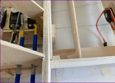
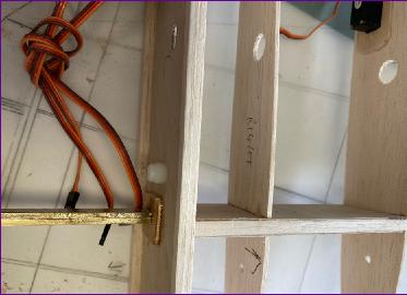
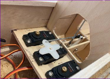
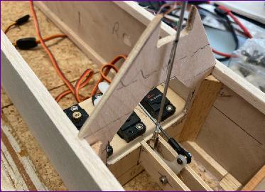
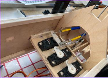
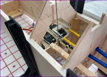
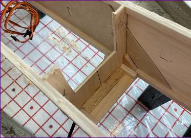
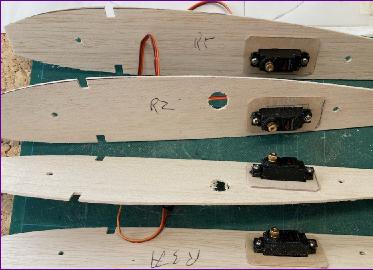
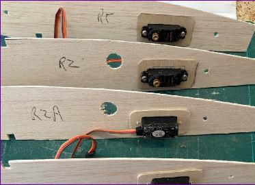
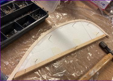
Tail End The tail surfaces are shown as solid sheet balsa so, in enlarged form, it may be worth using a sheeted built-up structure instead. Whilst the fin is on the small side, the tailplane is generously proportioned. However, the tail moment arm looks a bit short. I don’t want to lose the character of the prototype but longitudinal stability is important for a tug so I decided to lengthen the rear fuselage a bit. Since I need to build in a tow release behind the cockpit, I reckon that’s the best place to perform the ‘stretch’. Other mods needed at the rear include a steerable tailwheel and possible provision for rear mounting the elevator and rudder servos, depending on how the cg works out.
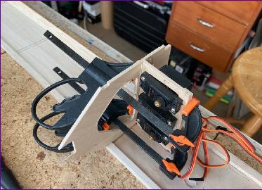
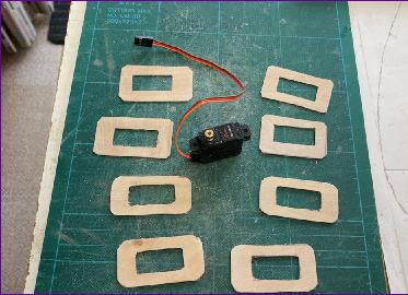
Front End This will be an electric model of course and my selected motor is a lot smaller than the enlarged drawing of an i.c. engine on the plan. A new firewall was drawn in to mount the motor and the details of the cowl structure were left to be considered later.
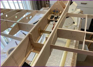
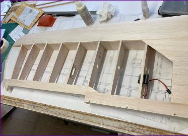
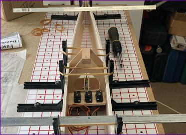
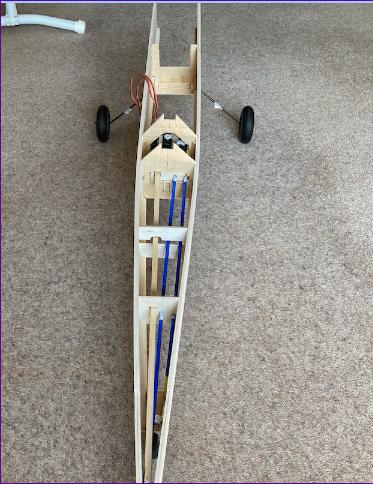
Midships While making these mods to the fuselage side view, I had a look at the question of battery placement. If I really was going to have the option of fitting a second battery just for towing duties then, whereas battery no.1 can sit happily in the ‘tank bay’, the second battery really ought to be as close as possible to the cg. With a slight adjustment to the cockpit floor it looked like there was just room to fit this optional second battery over the wing. To give easy access to both batteries the hatch logically should extend from just behind the firewall to the back of the cockpit. It was all looking good until I suddenly realised that, with the wing and the hatch removed, the front and rear fuselage sections would be joined only by the upper fuselage sides which, in spite of the slightly thinned wing section, would only be about 1/2in high over the thickest part of the wing!
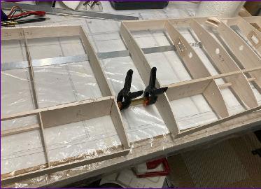
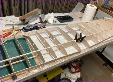
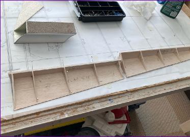
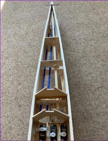
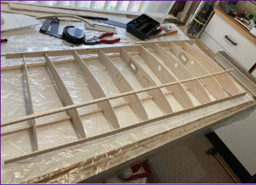
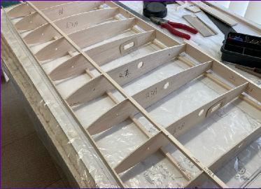
This realisation sent me back to the wing again, re-drawing it in the form of two plug-on panels so that the integrity of the fuselage sides could be preserved. It adds a bit of weight and complexity but, by way of compensation, this arrangement also frees up a bit more space in the fuselage for the optional second battery.
There are lots more minor issues and modifications to be tackled as the build progresses but at this point I reckoned I had a sufficiently stable baseline to make a start - except that it was only mid-August and I have a self-imposed rule of not starting a ‘winter’ build until September. This sometimes seems like a singularly pointless rule - after all, nobody else cares if I start cutting would in August! However I have to admit that, but for this rule, there is every chance that I would by now have been well on the way to building a one piece wing before the above structural problem dawned on me, so this time at least, a bit of delayed gratification has paid dividends by hopefully avoiding a lot of frustration later on. |
||
 Selection
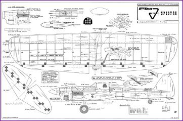 Conversion
|
||||||||||||||||||||||||||||||||||
|
||||||||||||||||||||||||||