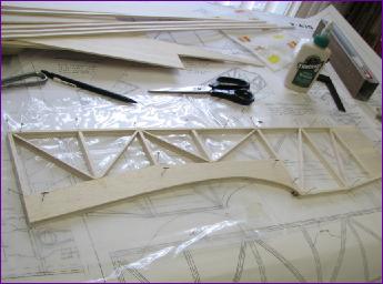
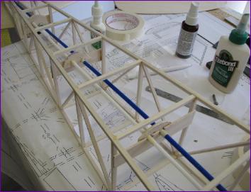
The fuselage sides are shown as built from 1/4in square balsa. To save a bit of weight, I used 3/16in sq and reduced the diagonals to 3/16 x 1/8in. The two sides were built one over the other, the first one being turned over before building the second, with a sheet of polythene in between.
Two formers were fabricated from 3/32in balsa fore and aft of the wing seat instead of the solid 1/4in bulkheads shown on the plan, although the lower sections of these get reinforced to take the wing fixings.
A fair bit of 1/4in balsa was omitted from the front end of the fuselage sides too, but there are still some decisions to be taken in this area once more is known about the power plant and battery position.
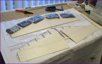
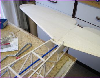
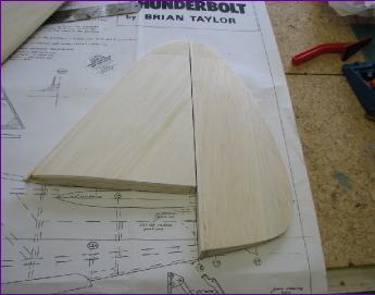
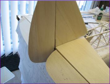
No, I didn't build two tailplanes! Top and bottom half shells are built and skinned before being glued together. This technique was new to me but it did seem to be quite a good way of building a symmetrically sectioned surface.
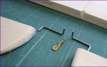
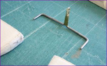
I opted not to bother with the complication of scale hinges, so built an elevator joiner/horn using my preferred method of piano wire and brass tube. For me, this always seems more secure than silver soldering a flat horn onto the wire. In fact I usually duck the soldering challenge completely by just epoxying the brass tube onto the wires.
I did a trial fit of the elevator snake at this stage, just to check that it would clear the retracted tailwheel. Shame I didn't look at these pictures again when the time came to install the snake for real!
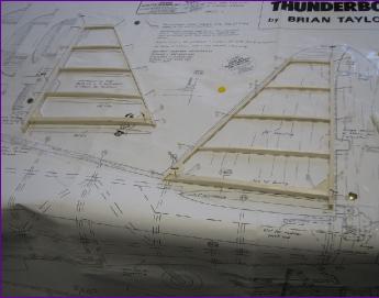
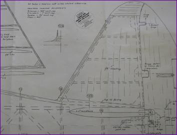
The fin is constructed in two half shells, just like the tailplane. Although all the ribs are drawn on the plan, there is no indication of how the fin is attached to the fuselage. The normal technique of extending the bottom of the fin post down into the fus is a bit problematic because the rear edges of the fin and tailplane coincide.
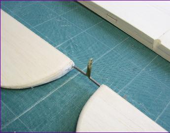
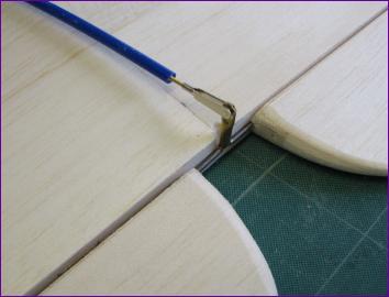
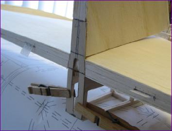
Once the fin and rudder were built, I let a 1/16in piece of ply into the rear of the fin and cut a corresponding recess into the tailplane, so that the fin could be attached to the rear of the fuselage framework.
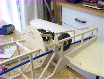
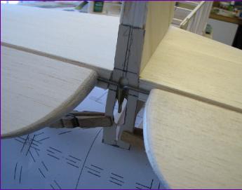
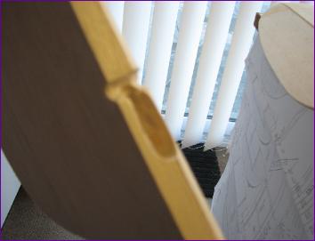
In fitting the fin post extension, I had to make a cutout to accommodate the elevator horn and it was only then that I realised that application of up elevator would push the elevator horn back into the rudder. Fortunately the rudder is sufficiently wide to he hollowed out to accommodate this movement, even when the rudder is deflected. Sorry about the focussing failure of the second photo, which is trying to show the pocket hollowed out in the rudder.
After all this 3D puzzling, it came as quite a surprise to see how neat the finished tail group was. Much neater than the full size in fact, due to the simplified hinging arrangements.
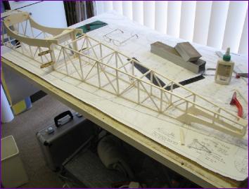
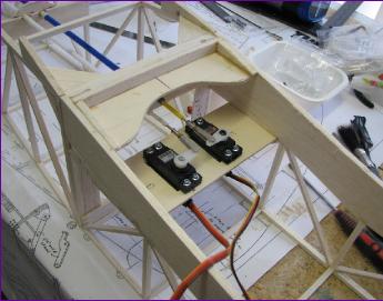
With the tail surfaces in position, the servos and snakes were installed. I was really pleased at how straight I managed to get the snakes and it was only after all the supports had been fitted that I found that they fouled the retracted tailwheel so the supports had to be cut free again to allow the snakes to be re-aligned. They are a bit more snaky now!
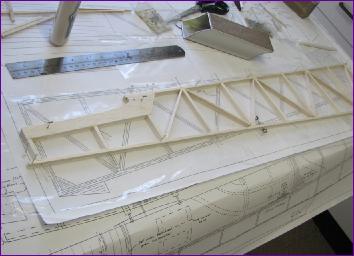
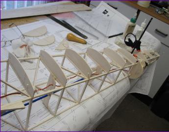
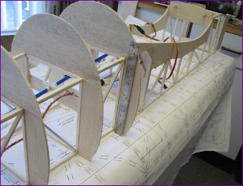
Once the tailwheel steering link had been sorted (see main diary entry), I started on the side and lower fuselage formers. At this stage the fuselage frame is still sitting nice and flat on the bench and, even before that tall razorback superstructure is added, my six inch ruler is dwarfed by this bulky fuselage.