It's seven years since I did the electric conversion of the Air Loisirs ARTF MiG 3. The MiG flies well but, at the end of the day, it is still an ARTF and I have never really bonded with it as a model. Part of my grand space-management plan is that each new model must be accompanied by the disposal of an existing one, so, when looking for a new build project, I homed in on the idea of a WW2 fighter to take the place of the MiG.
When it comes to warbirds, my ineptitude with all things brush-related does tend to limit choice somewhat - anything with camouflage colouring is a non-starter, for example. Mind you, I have always thought that camouflaging a remote controlled aircraft wasn't really a good idea anyway! Much as I like many of the RAF fighters, the USAF ones offer more scope for colour schemes that can be implemented in heatshrink film and vinyl and so, after a bit of deliberation, I homed in on the P47.
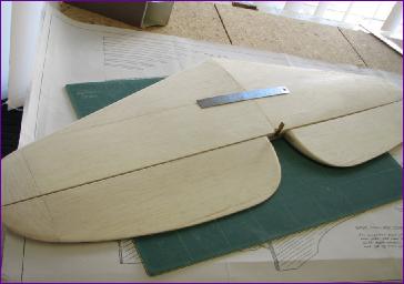
The MiG is 60in span and so the Brian Taylor design, at 76in span, was always going to be a bit bigger. However, it wasn't until the plan arrived that I realised just how hopeless my idea of slotting the P47 into the space vacated by the MiG was. Whereas the Mig is a bit Spitfire-esque, with a svelte fuselage and fairly high aspect wings, the P47 is a big brute of a plane with relatively short, stubby wings. Not to put too fine a point on it, the fuselage is HUGE. No matter, by now I was mentally committed to the project so I began by pondering the most critical aspect of any warbird build, the retracts.
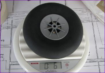
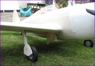
September 2013 The Hobbyking electric retract units fitted to my DH88 Comet have proven to be very reliable so far and, although the 76in P47 will certainly be somewhat heavier than the 80in Comet's 6lb 4oz, the fact that those retracts are now available with all-metal trunnions, rather than the plastic/brass versions used on the Comet, encouraged me to order a pair. While awaiting delivery of the retracts from China, the wheels arrived. These confirm what a beefy machine this is - they are 5in in diameter and, even at just over 6oz apiece, don't feel particularly heavy for their size. However, when I put one of them on the end of a ruler and picked it up at a point to simulate the length of the u/c leg, doubts started to creep in.
Sure enough, when the retracts arrived they really couldn't cope with the task of hauling up those wheels on such a long leg. Whilst it might have been possible to rig up some counterbalancing springs, I really had to admit to getting it wrong - at least I now have a spare pair of retracts for the DH88!
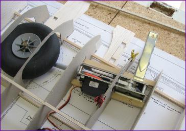
After a bit of a hunt around for some heavier grade retracts, I happened across a pair of Robart mechanical units made for the original Hangar 9 150 sized P47. This model was slightly bigger than the Brian Taylor one (81in span vs. 76in) but I felt that such a slight difference could be accommodated so the order was placed.
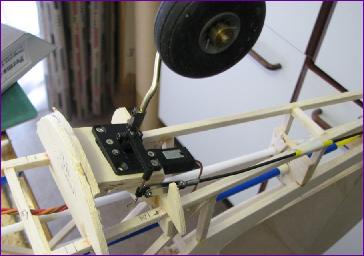
As you can see from the next picture, these are very substantial units. They aren't too heavy but the main problem was that, when I fitted a pushrod and clevis to the mechanism, I couldn't raise the wheel, in spite of the help of the counterbalancing springs. I took one of the units along to a club meeting and, several sore hands and one severely bent pushrod later, the consensus was that they couldn't possibly work!
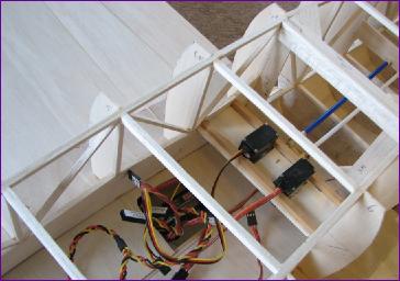
Undaunted, after a bit of research and cogitation, I ordered a pair of Spektrum A7000 retract servos and, after fitting some heavy duty servo arms (the originals just twisted under the strain) surprise, surprise we have lift off - or at least lift up!
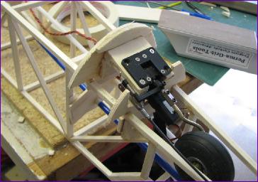
The next issue with these retracts is the mounting. They need to be installed with the servo already fitted, so it is hard to visualise just how much manoeuvring space is needed. Also the mounting angle is clearly going to be different from the Unitract units shown on the plan and lastly, when tilted to the appropriate angle, they are just a bit too tall to fit in the wing section.
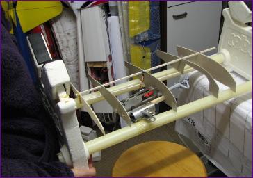
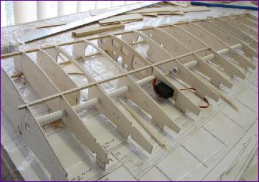
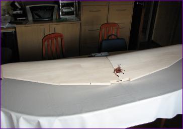
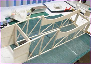
Clearly, some experimentation was going to be needed so I cut out a set of cardboard ribs for the inboard section of the wing and, with a pair of 3/8in square Basswood bearers, constructed a fairly precarious first mockup of the installation, just to get an idea of the angles, and by just how much the wing depth was going to have to be increased.
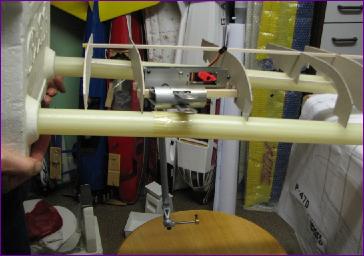
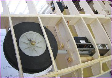
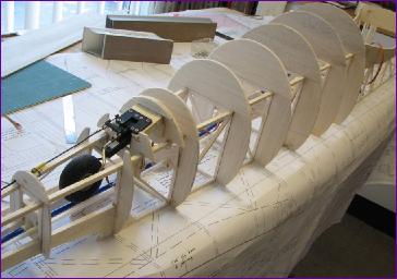
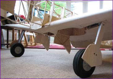
After a bit of fiddling with the angles, the next step was to shorten the oleo legs by half an inch or so, then a second mockup was put together still with the, by now much modified, cardboard ribs.
You can see from these pictures that, even with the increased wing depth, the wheel is a tight fit, so, by the end of the month, I was wondering whether I might do better with some skinnier wheels. Thinks - is this going to be one of those projects where everything has to be bought twice?!
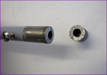
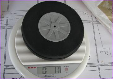
October/November 2013 (more on November) I eventually found some thinner wheels. In truth, because the hubs are not dished, the depth required in the wing is not much reduced. However, the model has just got half a pound lighter!
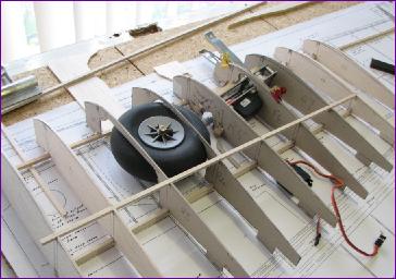
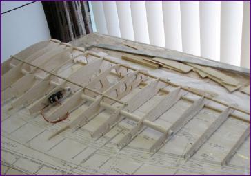
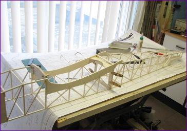
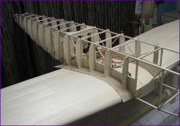
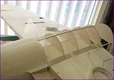
Eventually, I had done all I could on the fit of the retracts so it was time to replace the cardboard ribs with wooden ones and start glueing them in place. The root ribs were omitted and R6 was left unglued, pending yet another trial fit of the retracts. R6 sits between the retract servo and the retract itself and is vital to support the mounting bearers but also tends to obstruct the insertion of the retract unit so its position is very critical.
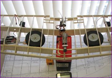
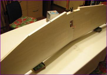
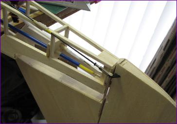
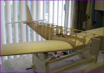
After a bit more work on the framework of the wings, they were robust enough to be temporarily joined, with the retracts in place and I couldn't resist the temptation of having a play with the sequencing facility on my Jeti DS16 transmitter. The servo balanced on the top of the wing represents the inner door operation, just to check on the timing of the sequence.
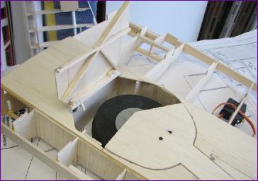
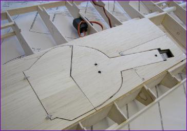
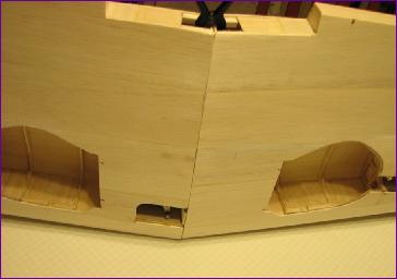
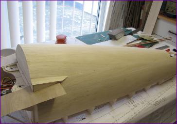
The next stage was to embark on the skinning of the wings with 1/16in balsa. It took me some time to decide on how best to tackle this. In the end, I opted to get the underside area around the retracts done first. This was quite an involved job, so there was a four week gap between these photos and the next ones - hence the combined October/November diary entry! More details of the retract installation are on the November page.
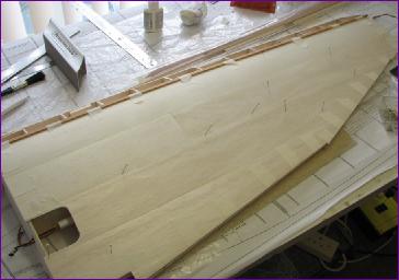
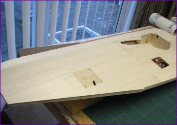
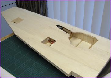
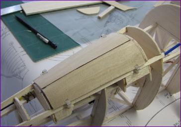
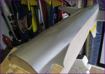
With the complexity of the retracts out of the way, it was on to sheeting in the upper surfaces, then chopping the 'feet' off the ribs and sheeting in the remainder of the undersides. Along the way, the ailerons and flaps were also built up and skinned and the process of joining the panels was rehearsed, just to be sure that it could still be done after the sheeting!
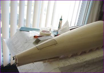
The undersides end up being a bit of a patchwork, what with hatches for the aileron and flap servos as well as the retract hatch, fairing and door. Perhaps it's no wonder then, that there were a few dips and bulges to be sorted out, whereas the top surfaces so far are a filler-free zone.
That brings us to the end of November. I plan to move on to the wing tips and leading edges before finally joining the wing panels together. Hopefully the new year will see the wing plans rolled up to make way for the fuselage.
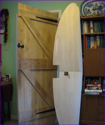
December 2013 Having been a bit tardy with the last diary update, I thought I'd get ahead of the game this time! Once the leading edges and tips were fitted, there followed several days of alternating filling and sanding before eventually there were no excuses left and it was time to join the wings. After innumerable dry fits and adjustments during which I struggled to get the wings propped up at the right angle, I finally decided to join the panels propped up on their leading edges.
Copious amounts of epoxy were mixed but, as soon as I started applying it to the root ribs, it quickly became clear that it was nowhere near enough! Whether it was the stress of joining the wings for real or just trying not to get epoxy everywhere, somehow I managed to drop one of the wings in the process and then, when coaxing the wings into place, break a couple of pieces of sheeting off around the wheel wells. Eventually though the job was done and the joint seems to have worked out okay.
Once it was all dry, the broken bits of sheeting were repaired and reinforced on the basis that, if I managed to break it this time, I would sooner or later break it again!
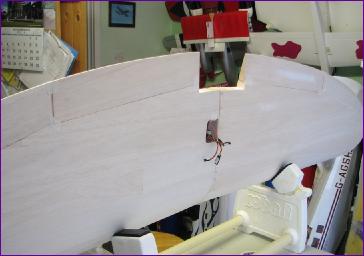
Next I installed the wing-mounted receiver and tested out the retracts, gear doors and flaps, which resulted in yet another round of trying to get the fairings to align nicely with the underside of the wing.
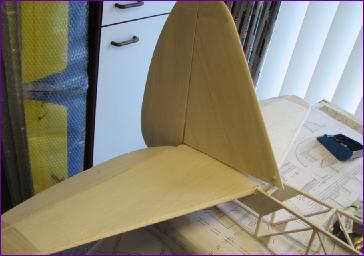
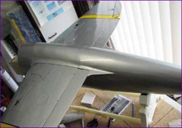
With the flaps and ailerons taped in place, the full expanse of the wing becomes clear for the first time.
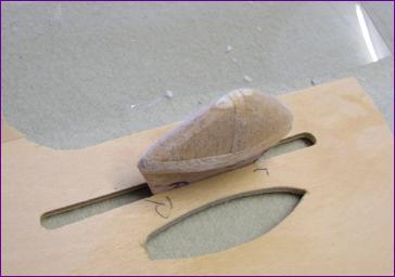
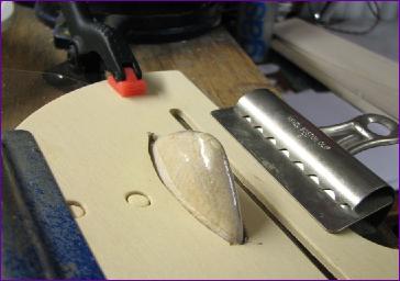
Last job of the month was to mould the lenses for the nav lights on the wingtips. This was done using the pieces of balsa cut out from the wingtips as a plug. With the aid of a suitable aperture in a piece of scrap ply and a heat gun, the plunge moulding process was straightforward, but it did take me three or four attempts to get a satisfactory result - surprising how heavy a gauge of plastic was needed.
Anyway, the wing has now been put aside for Christmas and I hope to start the fuselage in the New Year.
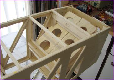
January 2014 (more on January) The fuselage sides were constructed in two sections. After the front sections were joined, the rear sections could be added and cross pieces fitted. I added in a leading edge mounting bulkhead and ply plate for the wing bolts at this stage too.
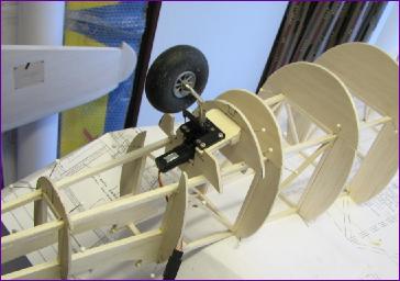
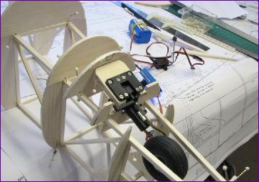
Brian Taylor's plan shows a home made retractable tailwheel assembly, but I decided to use a commercial electrical unit. This is actually a steerable nosewheel retract intended for a much smaller model. Time will tell if it is up to the job but the only steerable, retractable tailwheels I could find were either too flimsy or too butch and expensive. Choosing this unit meant that I was on my own as far as mounting was concerned so much juggling about with cardboard templates etc. was needed before settling on the arrangement temporarily lashed up below.
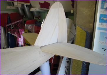
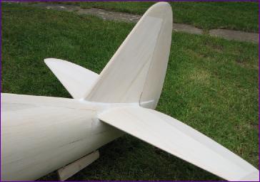
At this point I realised that the steering linkage to the tailwheel would have to connect from the rear so it would make sense to drive it from the rudder. The tailwheel bits were therefore put aside whilst the tail surfaces were built.
The elevators and rudder are just 1/16in balsa skins over a simple framework rather than the hollowed out solid balsa construction shown on the plan. Details of the construction of the tailplane and fin can be found on the January Diary page.
With the tailgroup sorted out, the tailwheel could finally be fitted for real, and the steering linkage sorted out. The steering is by a rigid pushrod and you can see in the pictures below that, when the wheel is retracted, it is automatically centred and the connecting link slides back and forth along a rod.
The next challenge is to work out how the tailwheel doors will be fabricated, hinged and actuated. Before that though, I needed to add some shape to this huge fuselage so that I can better judge the profile of the doors.
February 2014 (more on February) The tailwheel doors were laminated from two layers of 1/64in ply and a balsa framework subsequently added. (see the February diary entry for more details). Hinge positions were a guesstimate at this time and, although I thought I had made due allowance for the fuselage skin thickness, this turned out not to be the case later on!
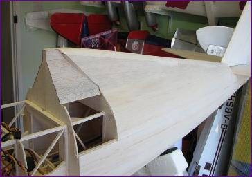
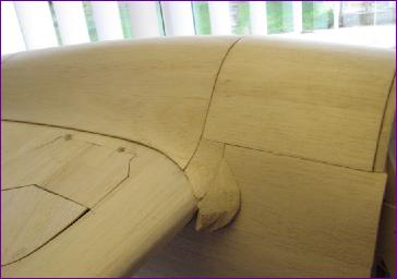
Next job was the wing seating. Once a satisfactory fit had been achieved, the 1/64 fairing baseplates and side formers could be fitted.
There's one receiver in the wing to control flaps and retracts. A second receiver will be installed in the fuselage (probably alongside the servos) to handle the primary flight controls.
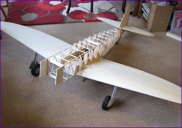
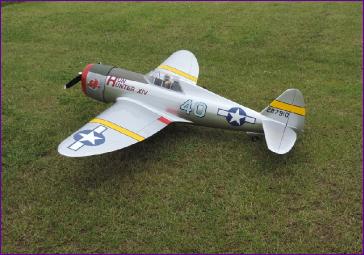
With the wing fitted, I couldn't resist the temptation of putting it all together and standing the model on its wheels for the first time. (more pictures are on the February Diary page)
And of course, I shot another retract video, this time with tailwheel and all doors operational!
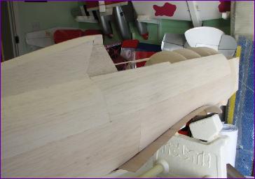
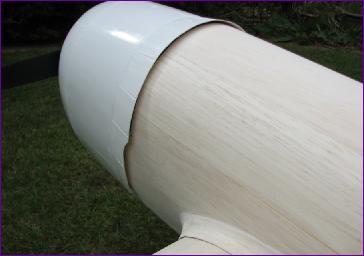
The plan shows the rear of the fuselage planked from 3/8 x 3/32in balsa strips. However, I found that soft 3/32in balsa sheet could be persuaded round the fairly modest compound curves which saved a lot of time. All this saved time (and probably more) was though spent on re-fettling the tailwheel doors which suddenly seemed too big, not curved enough and with badly aligned hinges. The end result blends in well enough though.
Last construction job of the month was to make the underwing belly fairing. I decided that this should be detachable so that the wing bolts can be completely concealed. It also gives me the option of retrofitting a servo and release mechanism for the drop tank.
So the formers were stood on 1/64 ply edging strips and the framework covered in 1/16in balsa.
The plan is to keep working forwards, delaying the detail of the battery stowage as long as possible so that I can get a feel for the balance of the model.
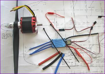
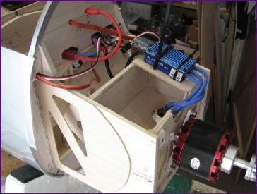
However, as a taste of what lies ahead, The main power plant components arrived towards the end of the month. Current AUW forecast is around 10lb and planned power is an 8s x 3300mah LiPo driving a 250rpm/volt motor. Once I have managed to do some power checks, I'll take a view on whether a scale four-bladed prop is likely to work. Meanwhile, I think there is at least another month's woodwork still to go. . . .
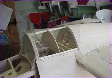
March 2014 (more on March) The first job of the month was to add the important bits at the front and rear so that I could get a first idea of where the batteries were going to have to go to balance the model.
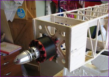
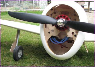
The fin was temporarily fitted in order to line up the turtle deck and work out the rear cockpit. Then the motor was temporarily mounted. At this point, the 3/16in square fuselage framework was under some strain and everything had to be handled with care.
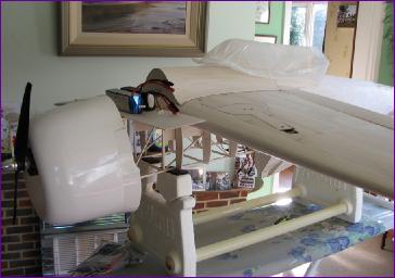
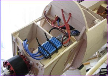
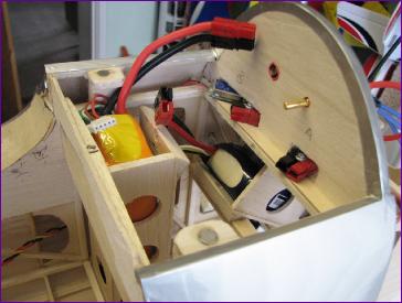
With the cowl hung in position and two 4s 3300mah LiPos perched on top, the model just about balanced so, on the basis that the cg is only going to go rearwards from hereon, I decided to mount the batteries as far forward as possible.
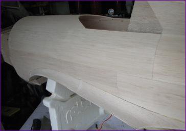
The battery boxes are removeable. You can also see that I took pity on that 3/16in framework and fitted 1/16in ply doublers, heavily fretted out. With the battery stowage sorted, I felt confident to press on and sheet in the fuselage sides.
The batteries will be inserted through a belly hatch between the wing leading edge and the back of the cowl, so this was the next bit to sort out.
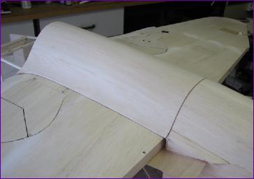
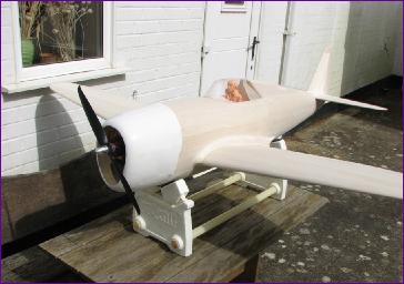
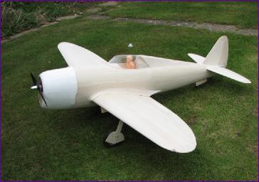
Eventually the job of the overwing fairing could be put off no more. Once this was done and the wiring installed, the model was assembled for the traditional bare photocall. There's more detail on the fairing construction and the wiring arrangements on the March Diary Page.
This was a very satisfactory stage to reach at the end of the month, with just a few days preparation needed before a start can be made on the covering. However, preparing the model for this photoshoot highlighted a few points which need further thought: As you can see from the last picture, a dummy engine of some sort is going to be essential. Also, the power test with the two bladed 18 x 8 prop shown in the pictures only drew a modest 25amps. This suggests that it may be possible to use an 18in four bladed prop so I'll be looking into that further. The balance check also showed that the cg was now about 1.5in forward of the designated spot, so I might have got a bit carried away in my efforts to get the batteries as far forward as possible. However, I'll check this again after covering before contemplating re-working the battery boxes.
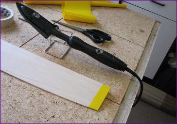
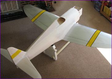
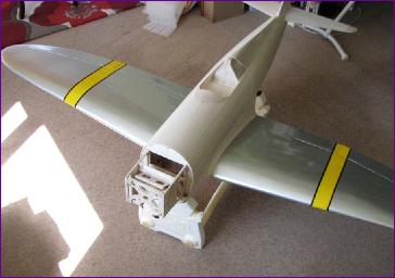
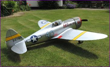
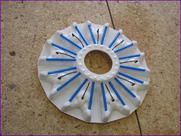
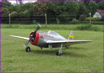
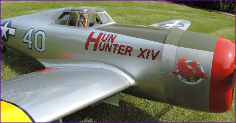
April 2014 Before unrolling the 10m of silver covering, I thought I'd start on the yellow stripes. For some reason, on my chosen prototype (Hun Hunter XIV) these stripes straddle the aileron/flap joint so, for the wing stripes alone, a dozen pieces of yellow film are involved.
Then it was a case of nine days ironing to reach the stage shown below. Actually, it wasn't all ironing - the undercarriage fairings and inner doors were fitted for hopefully the last time and the flaps and ailerons have been hinged and linked so the wing is very nearly finished.
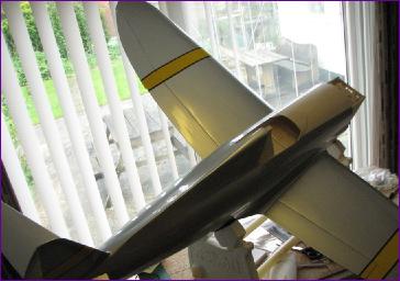
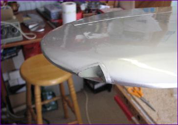
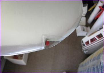
Tailplane and rear fuselage underside were next on the agenda, followed by the wing fillets. I tried to be realistic about how much of the fillet to try to cover with each piece of film, on the basis that a neat joint is less unsightly than the inevitable wrinkles and creases that arise from fighting the film into places it doesn't want to go.
They do look a little rough close up, but the overall effect isn't too bad.
Fuselage sides, fin and rudder were then tackled followed by the underbelly fairing and hatch. The antiglare panel will wait until the cowl comes back from painting so that the edges of the panel can be aligned with the cowl flaps.
Having got the wings out for these photos mainly to verify the fairing and hatch fit before covering them), it seemed a good moment to sort out the nav lights. The LEDs which I had in stock turned out to be too big so I rounded off the end of some 1/4in dowel and painted it. The result is pretty crude, but scale detail nver was my strong point.
With that thought in mind, it's on to the cockpit detail now. . . .
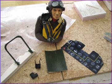
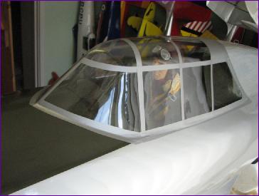
May 2014(more on May) The instrument panel, gunsight, seatback and armoured screen are my own work but the pilot was painted for me by a more artistically inclined clubmate. The rest of the cockpit was left plain but, once it was all assembled, I was happy with the overall effect.
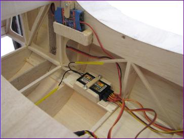
Next, the wiring was tidied up and the receiver and two uBECs mounted in the fuselage.
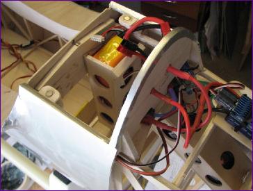
Somehow, I made a major misjudgement about where the batteries would have to go to achieve tha required cg so the last job was to re-mount the battery boxes vertically, directly ahead of the leading edge bulkhead, rather than inside the cowl area.. These two pictures show one pack in the old, forward position and another in the new, vertical location. Even so, the model was still a little nose heavy but that's not necessarily a bad thing for a maiden flight.
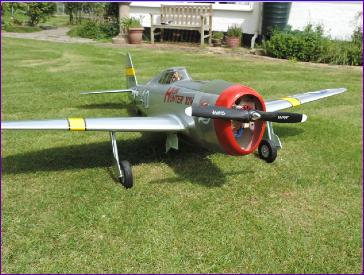
The model was taken outside for a photo call and taxi trials. During this process, one of the undercarriage legs rotated very slightly. This prompted one more check on the security of all fixings in the undercarriage since any movement could easily result in a major jam involving wheels, legs and doors, possibly leaving it all hanging out to be ripped off on landing.
At this point, the weather deteriorated and a week or more went by without any prospect of flying weather, so I made a start on the dummy engine. The pushrod tubes are cut from snake outers and the ignition wires are, well, wire. More pictures of the dummy engine can be found on the May diary page.
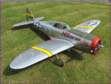
Eventually, on the last day of the month, the weather relented and so it was off to the field, where these last two shots were taken, immediately before the maiden flight.
I had decided to do a fast taxi run just to check that the retracts didn’t shift at all - my biggest worry was that, if the retracts failed to go into the wells for any reason, the servos wouldn’t give up without a struggle and then, just to complicate things, the inner doors would try to close and, if that didn’t break everything, landing on it certainly would.
Anyway, so fretful was I about the retracts, that it was only at the last minute that a more fundamental problem was spotted - reversed ailerons! I can’t imagine how I failed to spot that in any of the umpteen previous test assemblies this model has been through, including the garden taxi trials. This sobering discovery at least resulted in me applying rather more diligence to the rest of the pre-flight checks. I even did a range check!
The results of the taxi trial and maiden flight are shown in the video. In summary, the model needed a lot of up trim and felt very nose heavy. Fortunately my Jeti Tx has an Autotrim facility so I was able to get it trimmed out without taking my thumbs off the sticks. After a couple of circuits, I dropped the gear and deployed half flap and went through the trimming process again. The model was landed safely but I think you can see from the video that it ran out of elevator authority in the flare.
A random chunk of lead (subsequently weighed as about 1oz) was taped to the tail before a second flight, and I also unrated the elevator - something that never crossed my mind during the anxiety of the maiden. This time, the controls were much more responsive and, although most of the up trim remained in place, I no longer felt that it was a struggle to hold the nose up. One loop and one roll confirmed that the control throws were reasonable and that the power level was adequate but not excessive.
The other issue that arose was that the belly hatch popped off immediately after takeoff on the maiden flight. For the second flight, a rubber band was put around the fuselage - and the hatch stayed in place until the roll, whereupon it again departed the scene. I’ll clearly have to devise a more positive fixing (it’s just magnets at present) or rely on the dummy engine to cut down the ram effect and maybe cut some operational (but scale) vents into the fuselage.
So, lots to do still, including yet another battery relocation exercise, dummy engine and four bladed prop, but happily, no repairs!
I seem to have reached the limits of my HTML editor in some way so this diary is continued in Part 2.
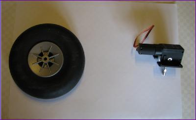 Sure enough, when the retracts arrived they really couldn't cope with the task of hauling up those wheels on such a long leg. Whilst it might have been possible to rig up some counterbalancing springs, I really had to admit to getting it wrong - at least I now have a spare pair of retracts for the DH88!
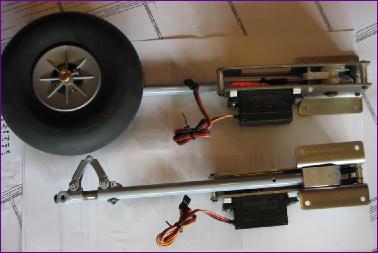 Undaunted, after a bit of research and cogitation, I ordered a pair of Spektrum A7000 retract servos and, after fitting some heavy duty servo arms (the originals just twisted under the strain) surprise, surprise we have lift off - or at least lift up!