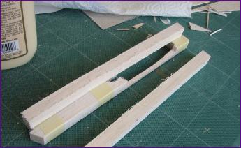
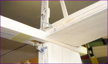
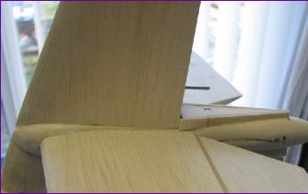
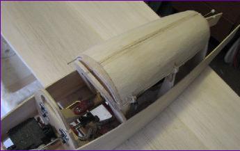
I spent a long time studying the photos of the full size to try to get my head round the shape of the bullet fairing around the fin / tailplane joint. In the end, I decided to build up a cylindrical former from four lengths of 1/2in square balsa. These first two pictures show the two lower sections relieved to fit over the fin and accommodate the tailplane.
Sanding the fairing to a cylindrical section caused the front and pack portions to separate, so the front portion was fitted first and the remainder of the fin built up. Then small 'fixed rudder' sections were built on the top and bottom of the rear fairing. Four headless pins were used for temporarily fitting the fairing to line everything up. When fitting these rudder sections to the fairing, the illusion of it tapering towards the front started to appear.
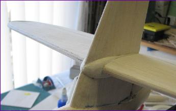
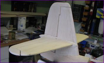
With the fairing put into position, the reason for the bizarre appearance of the full size suddenly becomes clear. It is indeed a cylindrical fairing the illusion of it being waisted around the hinge line being due entirely to the thickening of the flying surfaces at this point.
After building and hinging the upper rudder and a bit more fiddling with the elevator fillets (which need to be detachable so that the elevators can be fitted first), the tail group was at last pretty well done.
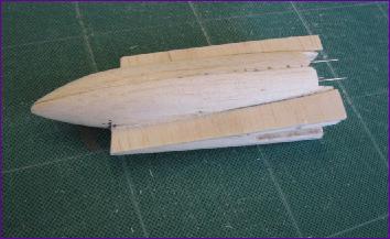
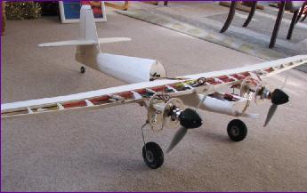
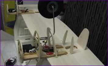
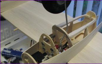
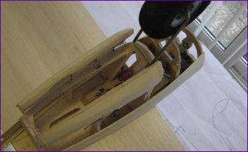
The wing joining arrangement is the conventional dowel and nylon bolt system. I was quite heartened by the sight of the model on its wheels but there is a bit of a problem with the battery location. It is possible to slide it under the wing into the position shown, but it won't be if the top half of the front former is fitted. I still haven't worked out how best to tackle this whole area of the removeable cockpit section and the shaping of the nose so put it off a bit longer by turning attention to the nacelles.
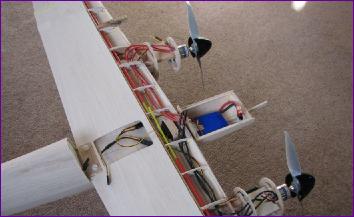
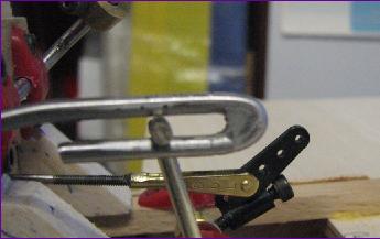
Because of the difficulty in forming the hairpin bends in the undercarriage legs (see September diary entry), they had been left over-long. To avoid any risk of the crank jamming in the end of the bend, the end of the hairpin was filled with epoxy and filed back just enough to accommodate the travel of the crank pin. With the retracts duly fettled, it was time to start hiding them away.
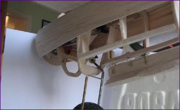
The former at the front of the bay is angled to clear the extended leg and the hairpin bend, as can be seen below left. Door hinges were fabricated from 1/32in ply and a crude closing mechanism made consisting of a length of closed loop trace running diagonally through the bay. This trace is pushed up by the retracting leg on the last part of its travel, closing the door.
Okay, they are still hinged temporarily with pins and the final shaping will have to wait until the rest of the nacelle has been sheeted in, but essentially the doors do seem to work.
Just to prove the point, the video clip on the left shows the doors in operation. The wheels do tend to catch a bit when pushing the doors open but I am hoping that this will improve once the inner surfaces of the doors have been suitably angled and smoothed. If not, I will have to look at some way of biassing the doors open, perhaps with a bit of mylar folded in the hinge line.