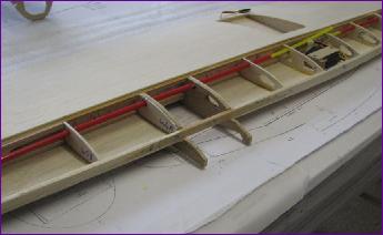
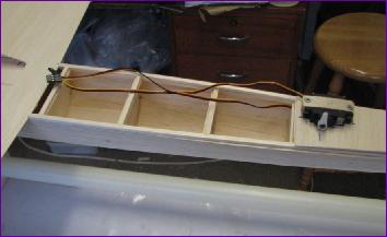
I remembered to fit the nacelle mounting doublers before inserting the snakes and was pleased to find that the nacelle bearers were a snug fit between them. If you enlarge the right hand picture you can just see the piece of spruce spliced into the false leading edge to help distribute the landing shock loads.
Mike's plan was drawn for a hand launch model. Having opted for retractable main gear - and resisted the challenge of a retractable tailwheel! - I did at least have to incorporate a steerable tailwheel mount. Then it was time to get to grips with the tailgroup, the picture below right showing the first of many dry fits.
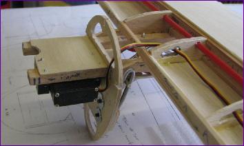
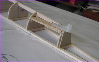
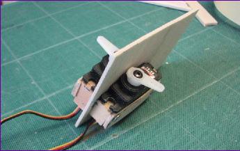
These pictures show the rudder and elevator servos mounted back to back on a balsa plate, which is positioned so that the servo leads do not need extending. Because the elevator servo becomes inaccessible once this plate is in position, I needed to sort out the elevator linkage first.
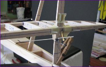
It all gets a bit complicated here! The angled pushrod from the elevator servo will link to the home-made elevator horn/joiner with a simple Z bend. The pushrod exits the fin post slightly left of centre in order to clear the vertical joiner wire which links the upper and lower portions of the rudder. This joiner runs in a length of aluminium tube and the assembly has to be manouvred into position as the tailplane is threaded over the fin post. The plan is to use the lower portion of the rudder to link this joiner wire to the tailwheel and also to carry the rudder horn.
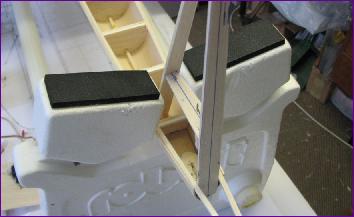
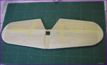
After working all that out, it came as a nice mental break to sheet in the tailplane and elevators.