HobbyKing Arctic Cat

I'd seen a couple of Arctic Cats being flown from the grass and was impressed by their sprightly aerobatic performance. Due to storage space limitations (and the ever increasing cost of Jeti receivers!) I've been trying to operate a 'one in, one out' policy for some time so this model looked to be a prime candidate as a replacement/upgrade to the Polar QT.


This model has been out for a few years but, like lots of others, was out of stock in the HobbyKing UK workshop for some time. However, earlier this year (2020) they came back into stock so I ordered one. At the time the Petrel build was occupying the bench so the model languished in its flat cardboard box for a few months.


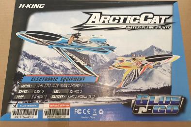
Said cardboard box sports a large sticker showing the two colour schemes available, a list of other parts needed and a "Glue 'n' Go" logo.


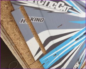
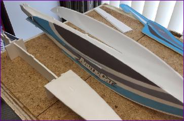
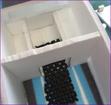
Inside, a large plastic bag contains a selection of pre-cut, pre-printed EPP parts and a smaller bag containing the ply pieces for the motor mount and a few linkage connectors, horns and screws. Apart from a bundle of carbon fibre strips and wire pushrods, that's about it.


Oh, I nearly forgot - there's a full coloured printed instruction book too. This was a pleasant surprise - early reviews of the model had bemoaned the fact that the instructions had to be downloaded off the web. The instructions have lots of photographs that are generally pretty clear, however there are one or two booby traps (such as the nose plate being shown the wrong way round alongside the sides to which it is to be joined). Also, as often seems to be the case, the assembly sequence has been chosen for ease of description rather than ease of construction, so it pays to look a few steps ahead and flex the published order a bit.
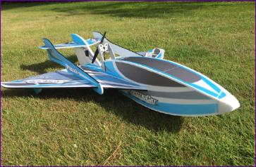
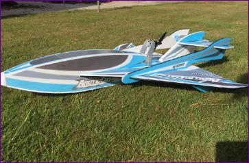
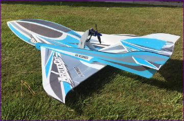
The biggest EPP sheet by far is the wing. This has to have carbon strips glued to its leading edges and a square carbon tube spar fitted into a groove on the underside of the wing. The latter is straightforward but the carbon strips have to be persuaded to cling onto the edge of the wing around some sweeping curves. I used UHU Por in contact adhesive mode for this which generally worked well, but the strip still tended to lift off in a few places.

There is some criticism on the web of the aileron 'living hinges', which apparently are prone to failure. If they are indeed supposed to have living hinges then, as you can see from the picture, one of mine was dead on arrival! The other aileron was still attached but didn't seem particularly secure so both ailerons were hinged with tape. The elevator and rudder are also hinged with tape but, whereas these are covered in the instructions, there is no mention of the ailerons. Did I mention that there are booby traps in these instructions?!

The fuselage (referred to as 'the nose' in the instructions), is basically a box of 5mm EPP, reinforced by an inner framework, constructed from slmilar material. The central inner keel has cutouts for the aileron and rudder servos. These cutouts needed to be deepened slightly to accommodate my servos (Corona CS-918MP). This job is clearly best done before assembling the framework. While I was about it, I adjusted the cutout in the fin for the elevator servo too. Another booby trap dodged.

Installation of servos is only addressed late on in the instructions with the result that the wiring is all rather messy. I decided to route the servo wires under the wing to tidy things up a bit. Obviously this isn't really possible after the wing has been fitted to the fuselage.

The rest of the basic construction progressed steadily, without any serious hitches.

Again, I opted to sort out the aileron and rudder pushrods at this point, before the side rails and tailplane were fitted. Looking ahead in the instructions again there is a comment 'Make sure prop don't touch pull rod when rotate'. So I did a dry fit of the motor mount and motor and quess what - even a 6in prop clashes with the rudder pushrod. Quite how one is supposed to make sure it doesn't is unclear, so I put a kink in the pushrod to bring it down close to the upper surface of the wing as you can see in the second pic below.

I seem to remember that the early publicity pictures for this model actually showed it without the motor and motor mount fitted, leaving it to the viewer to speculate on its method of propulsion. Perhaps no surprise then that the installation of the ESC and receiver also come rather late in the assembly sequence to my mind, with the result that the ESC is shown as mounted externally on the top of the fuselage. Whilst this is no doubt great for cooling, it's not ideal for a model designed to operate off water so I fitted the ESC internally, routing the motor wires through the servo compartment as shown below.

With the remainder of the construction done, apart from the top of the fuselage, the motor was mounted so that a cg assessment could be made to work out where the battery would have to go. As expected, it has to straddle the position in which you were instructed to insert a bulkhead some seven pages earlier! Fortunately, pre-warned by those who had gone before, I'd deferred fitting said bulkhead so it was a straightforward job to make the necessary cutout.

A generous strip of sticky back velcro is supplied for fixing the battery. I don't like velcro to my batteries so instead decided to use the bulkhead to retain the battery, in conjunction with a piece of non-slip matting. The only snag with this is that some of my batteries are somewhat swollen (particularly the Turnigy Nanotecs) so the aperture had to be big enough to accommodate these and a stepped wedge was made to secure the more slimline packs.

With the battery stowage sorted, the top of the fuselage could be cut into three pieces. The fore and aft sections were glued into place and EPP 'tongues' were fitted to the ends of the centre section so that it can be sprung into position.

The EPP noseblock was cut roughly to shape then glued on. It was then shaped with PermaGrit blocks although I must admit that I've never been able to get a smooth finish by sanding EPP foam.

During assembly I found that the paint was easily lifted by masking tape so, in the hope of preserving the paintwork, I gave the whole model a coat of Deluxe Materials Eze-Kote.

So, at the time of writing, that's where we're at. The model has been scooted around the lawn and seems to have enough power. The failsafe is set so, subject to a range test, it should be good to go. I'll report back once it has been flown a bit.