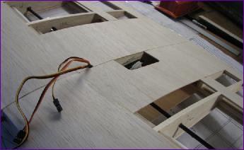
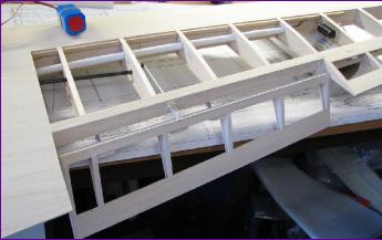
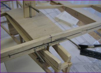
I left an aperture around the flap servo so that the clevis can be disengaged from the servo while fiddling with the linkages to the flaps themselves. The control surfaces were separated from the wing. If you enlarge the picture below right you can see the break point in the lower rear wing spar to accommodate the movement of the top hinged aileron.
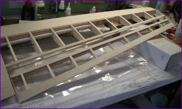
Top and bottom views showing the aileron hinging and linkage arrangements.
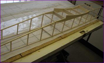
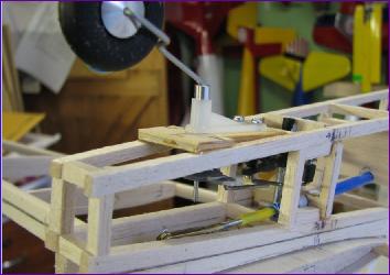
With the flap fully down, the clevis can be opened and adjusted to get the two flaps to work together properly. Don't think I will need that much flap in operation though! Once the leading edges and tips were applied and shaped, I had a major tidy up, got out the vacuum cleaner, rolled up the wing plan and unrolled the fuselage sheet.
Building the second frame directly over the first, with strips of balsa cut from the same sheet improves the chances of keeping the fuselage straight. I'm not sure whether the pieces of 3/16 balsa joining the sides across the wing seat are supposed to be there or not, but they seemed like a good idea.
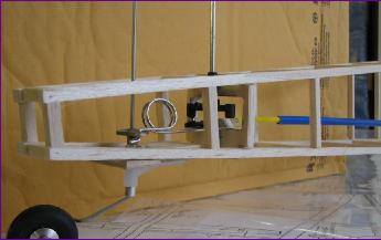
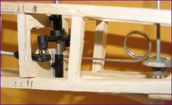
The next two pictures show the first feasibility test of the linkages at the rear end. I managed to fit a small wheel collet into a mixer bar from an old helicopter to make the rudder horn and relay the drive to the tailwheel. The pivot tubes and rudder torque rod are from a commercial aileron torque rod set. I eventually discarded the upper tube but it was useful while I was getting everything lined up. You can tell by the many marks on the longerons that this took a few tries!
The next two pictures show the final arrangement. Note the model is upside down in these and the mixer bar has also been flipped. The shock absorbing/adjustment kink in the tailwheel pushrod has also been re-orientated. The main reason for these changes was to make sure that the elevator snake (visible at the bottom of the left hand picture) would not foul the mechanism.
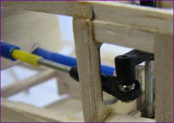
Just to complete the picture, here are the business ends of the rudder torque rod and elevator joiner/horn and also the tailwheel mounted on a 3mm ply plate.
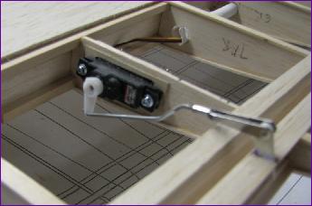
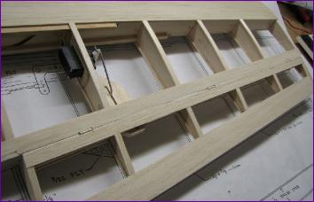
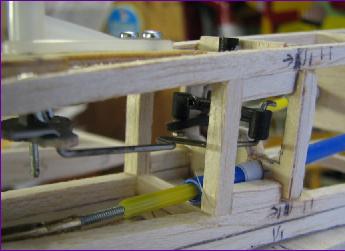
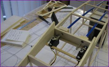
The rudder and elevator servos were mounted at the rear of the wing aperture in order to do a final check that the linkages worked properly and that the control throws looked sensible.
I will try to remember to put some threadlock on the grub screws securing the steering arms to the tailwheel and rudder pivot rods before the tail end is finally sheeted in.