As always, the thought process that led up to the decision to build this model was long and tortuous. Luckily for you, I can't remember it in sufficient detail to bore you thoroughly but suffice it to say that I started out thinking about building a canard, which somehow mutated via the Lear Fan and the Beech King Air before emerging as yet another Ivan Pettigrew design. Am I in a rut, I ask myself?
Actually, this was something of a joint decision. Three of us BIMBO members managed to talk ourselves into building Comets, so a joint build thread was started on RCGroups to swap ideas, discuss problems and equipment choices and chart our progress. This was back in July and, as I start to construct these web pages (in September 2011) the number of 'registered Comet builders' has reached seven; five in the UK, one in Norway and one in the USA, although only three of us have broken the seal on the glue bottle so far.
Preliminaries The above-mentioned RCGroups thread has all the detail, so I will just summarise the pre-build cogitations and preparations which took place during July and August, leaving the detail to the appropriate part of the build.
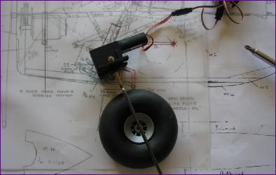
As you might imagine, choice of retracts was fairly high on the agenda. Ivan's plan shows home made units, which I used successfully on the Welkin. However, since then electric retract units have become available quite cheaply and, after researching on the forums, we eventually settled on the PZ-15091 units made by PingZheng Science Technology Co. Ltd. in China. Already, just two months on from making our choice, their range has expanded again.
The units seem to be well built and should be up to the job. They come with no instructions and no legs. There is though an alternative mounting plate, so the mounting flange can be above or below the unit. There is also a single machine screw, about 12mm x 3mm which, once you work out where it goes, is used to retain the leg. Initially, I felt that their lifting power was rather limited but, since re-charging the tired old receiver battery I was using, they now seem to have ample power.
Another area of discussion was the choice of power train. Ivan's model ran on 18 NiCd cells, pulling 30amps, with the motors mounted in series. I have more or less standardised on 3000mah batteries and usually aim to use about 2000mah in a 10min flight. That would imply an average current draw of only 12 amps. On a 3s pack, that equates to only about 140W which is a bit low for a model of this size (80in wingspan, about 6lb AUW) so I was keen to use a 4s x 3000mah battery if possible.
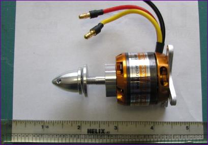
That is where I found I had backed myself into a corner. I really struggled find any motors in the 300 - 500W category with a low enough kv to turn a 12in prop on 4 cells for a current draw in the 20 - 25amp range. Eventually though, I bought two motors from RCTimer, specifically their BC3536-11 750kv offering.
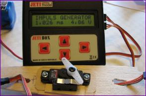
Preliminary tests indicate that these motors will draw between 20 and 25amps apiece at full throttle with 12 x 6in props on 4 cells so hopefully they should be just the job.
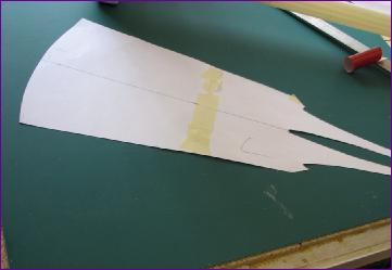
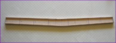
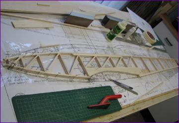
September 2011 As is my usual practice nowadays, I started with the wings: The full depth 1/8in balsa spar is joined at the centre but, because of the combination of sweepback and dihedral, this results in a tricky joint with difficult angles and not a lot of overlap. After a fair bit of cogitation, I decided to go for a three piece wing, eliminating the sweepback from the centre section spar to simplify the joint. I had some steel blade & brass box joiner section left over from the T61 so would use this to attach the outer panels, bending the blades to introduce the sweepback angle at the spar joint.
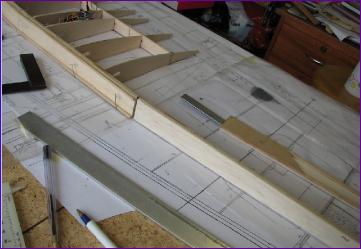
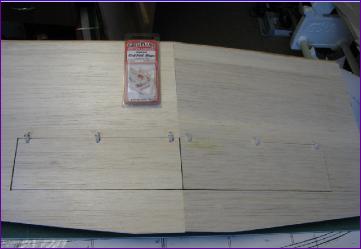
Thanks to the modest dihedral angle, the 1/8in central spar can now be cut out in one piece and the 1/8in sq spruce strips have a more generous overlap
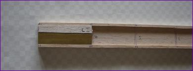
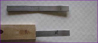
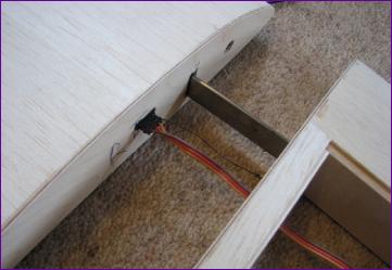
Next task was to build the brass joiner boxes into the ends of the mainspar and bend the steel bars to accommodate the sweepback.
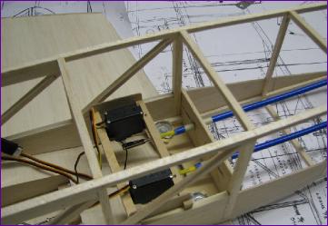
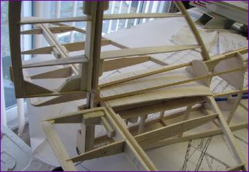
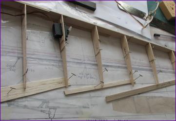
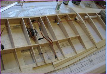
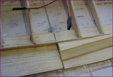
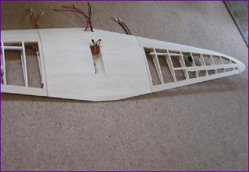
The rear portion of the centre section ribs was added next, with a rear spar 'egg box' joined to the ribs to provide a hinge line for the flaps.
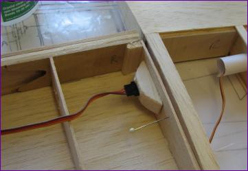
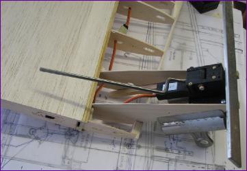
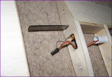
I mounted a microswitch alongside the flap servo to operate the landing light. This seemingly simple task seemed to take forever!
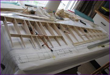
The outer spars were built, with the steel joiner bars expoxied in place. Then some ribs could be added to the outer panels.
October 2011 After assembling the wing for an alignment check, work continued on the outer panels. Cap stripping and sheeting, wing tips and leading edges added (although not finally shaped yet) and ailerons cut free, faced, hinged and linked.The incidence pegs were also fitted at this stage - carbon tube fitting into brass tube in the centre section.
Back to the Centre section again. The aileron connectors were installed, but the main feature of the centre section is of course those oddly positioned flaps. I fitted a small 1/16in ply dihedral brace into the trailing edge to restore some of the strength lost by cutting out the flaps, just to make sure the wing was strong enough to take the wing fixing bolts.
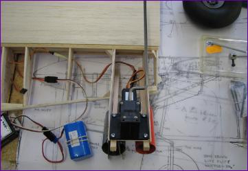
Once the flap pushrod arrangement was sorted out, I couldn't resist lashing up the wiring for the noselight and running a test:
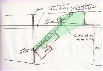
Before tackling the front part of the centre section, the problem of attaching the retract units had to be addressed. My first sketch showed 1/4in square bearers attached to a bulkhead at the bottom and glued to wing ribs at the top. It didn't look very secure to me and, after a discussion on RCGroups, I added the ply plates shown on the sketch in green.
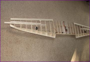
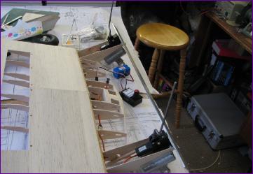
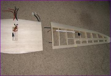
There was lots of trimming and test fitting before at last the whole lot could be dry assembled and checked for alignment.
November 2011 Once the wiring was in place, sheeting in of the leading edge part of the centre section could proceed.
Having snatched the aileron lead a bit when separating the wing panels, I installed thread tethers to reduce the risk of damaging the wiring.
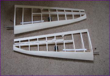
I had allowed for the fitting of 1/16in ply facing ribs to the panel joints, but it took a surprising amount of work to get them to mate neatly. The holes in the facing ribs are for retaining magnets but I will defer fitting these until after the model is covered so that the covering doesn't hold the magnets apart. This does mean though that, if the magnets aren't up to the job, my only 'plan B' is to tape the joint.
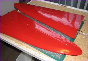
The final step before putting the wing aside for a bit was to make the wingtips, 'face and space' the ailerons and sand the whole thing.
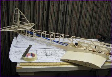
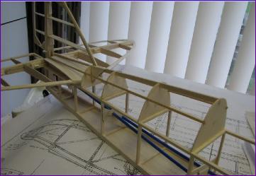
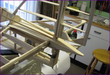
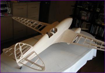
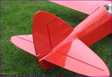
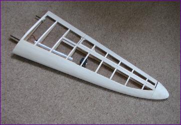
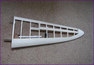
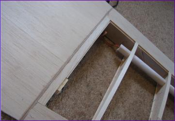
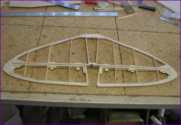
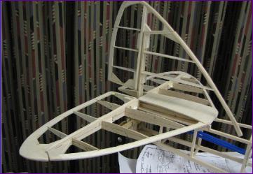
The two fuselage frames were built over the wing and joined together. Ivan has increased the tailplane area and, as you can see from the comparison with the 3-view, the shape has been changed quite a bit. I didn't want to compromise the model's flying qualities but decided to try to bring the outline of the elevators and the tailplane a bit nearer to scale.
Another consequence of Ivan's re-shaping of the tailplane was that the elevator hinge line came behind the rudder hinge line whereas they are the other way around in the full size. Again I decided to get a little closer to the original. The combination of this mod, together with changing the inboard ends of the elevators meant that care was needed to avoid the elevators and rudder clashing, and also to keep the two linkages clear of one another.
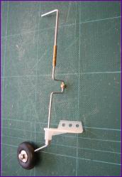
The one-piece rudder and tailwheel actuating rod simplifies things in one way, but it does have to be installed fairly early on in the proceedings. A ball link was threaded onto the wire during the bending process.
Apart from the tailwheel, everything else is just dry fitted at this stage.
With the servos and snakes installed and the wing fixing sorted out, things are at last beginning to take shape.
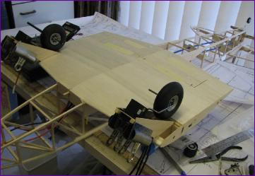
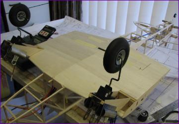
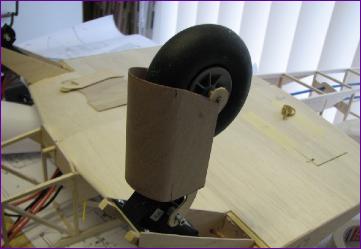
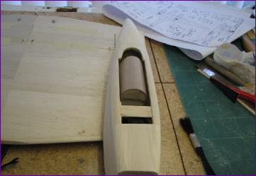
December 2011 (more on December) While the fuselage can still sit flat on the bench inverted, it makes a good stand for the wing centre section so this seemed like a good time to press on with the nacelles. The first job was to get the retract units aligned. What with the dihedral angle and the swept leading edge, this is not straightforward, although the decision to take the sweepback out of the spar did help a bit.
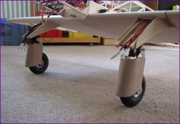
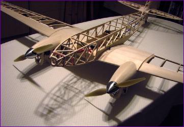
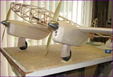
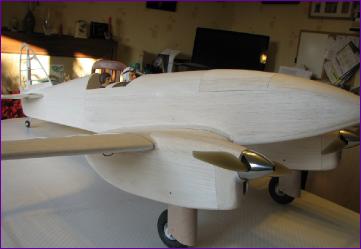
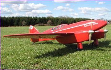
Next came the wheel fairings - there's more detail on the fairings and the u/c legs on the December diary page. Once the model could stand on its wheels, I just had to put it together and review the progress.
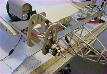
Mounting arrangements for brushless motors are totally different from the geared can motors that Ivan used so, as with the retracts, fitting the firewall was another 'make it up as you go along' job, with more alignment checks before gluing anything. It came as quite a relief to start planking over the top section of the nacelles.
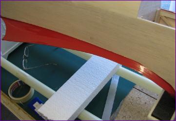
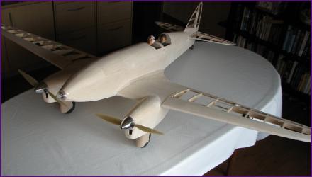
With this done, it was the first opportunity to get a rough idea of where the model was going to balance. As photographed, it it was pretty well on the mark without the battery on board so I think I can sheet in the fuselage without running into balance problems
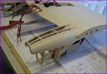
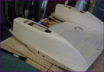
Meanwhile, the model was upended one more time to build the rear section of the nacelles, trying to get as close a fit as possible around those retracted wheel fairings. Again, more detail can be found on the December diary page.
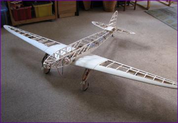
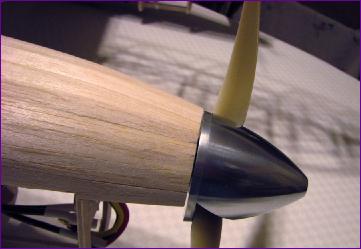
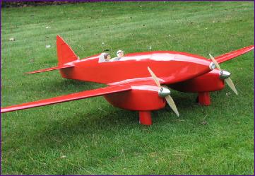
Finally the cowls were built and guess what? I had to put it all together yet again just to admire the curves.
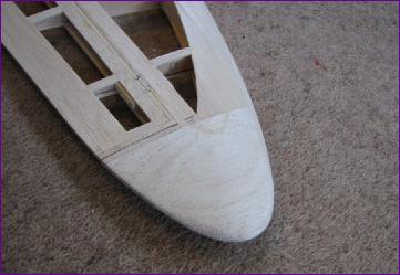
In the last few days of the year attention returned to the fuselage. The tail surfaces are now glued in position, the fuselage underside is sheeted in and the turtle deck and tailcone fairing are underway.
January 2012 (more on January) Once the tailcone frame was completed, the rear fuselage sides were added, followed by the turtle deck.
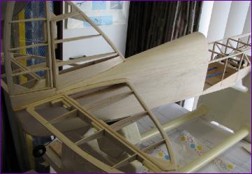
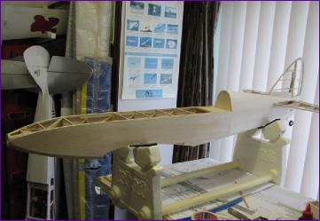
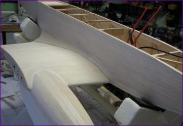
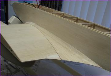
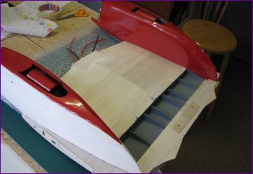
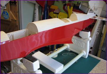
With the side sheeting completed, the fuselage was stiff enough to finalise the fit of the wing seat and move on to that large and characteristic wing fairing.
Details of the fairing construction are on the January page, but here are a couple of shots of the finished product.
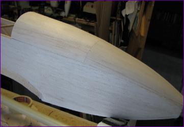
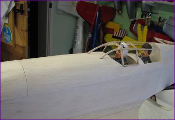
Next, it was just a case of working back along the fuselage top from nose to cockpit, via the hatch. The nose section was planked from 3/32in balsa. The hatch is from 1/16in sheet as is the rest of the fore deck The cockpit frame is from ply. The frame will need more work once it can be glued in place but meanwhile it has been put aside as a kit of parts while the model is prepared for covering.
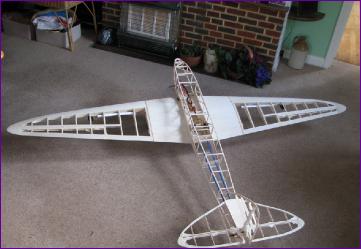
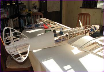
A very satisfactory position at which to end the month - the airframe is practically complete. Time for a big clean up in the workshop!
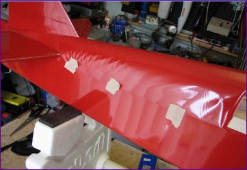
February 2012 February was all about covering. Because Oracover (previously known as Profilm in the UK) is now so expensive, I am using the Polyester covering available from GiantCod. This comes in 5m rolls, one of which will comfortably cover the airframe.
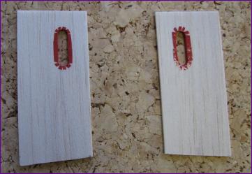
Covering around a hole is always tedious, especially when there is a pushrod emerging from it, so I was pleased that I remembered to line the holes in the aileron pushrod exit plates before fitting them. Next, the outer panels and ailerons were covered and the ailerons linked and hinged.
I covered the wheel fairings and the undersides of the nacelles then installed the retracts. The covering on the sides of the nacelles blocks the access holes to the screws retaining the u/c legs and fairings, but I will just have to poke through the film if (when?) the legs need to be removed.
The flap bay interior was painted before proceeding with the rest of the centre section covering.
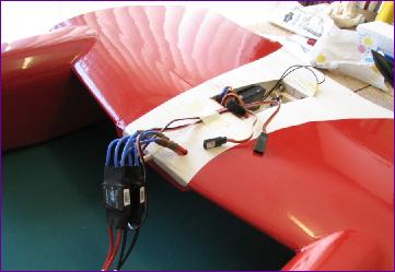
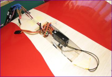
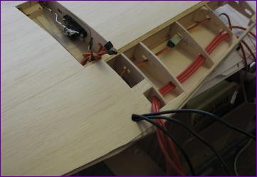
Before moving on to the fuselage, it seemed a good point to tidy up the wiring. By putting the receiver in the wing, the only flying lead connections needed are the rudder and elevator servos and the noselight. There's no airflow through the fuselage so the speed controllers 'hang loose' for maximum air contact. The speed controllers each have a digital BEC, one being used to power the retracts, flaps and noselight, the other for the receiver and primary flight controls.
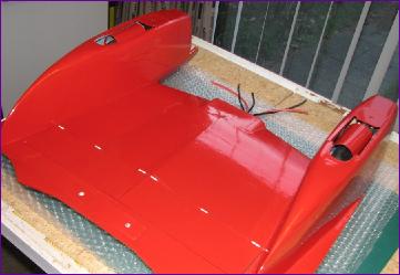
Wing fillets are always a struggle to cover so I like to get them done before applying the huge fuselage side pieces.
I was asked on RCGroups whether I use paper patterns for cutting out covering, to which the answer was a resounding "yes" - I can't imagine how it could be done without them. For larger pieces where positioning is critical, I sometimes find it helpful to tape the film in place until the initial tacking has been done with the covering iron. Incidentally, as you approach each piece of masking tape, it is always surprising just how much surplus maaterial seems to build up ahead of the iron.
With the airframe basically covered, I reckoned I deserved a break so once again the Comet was put together for a photocall.
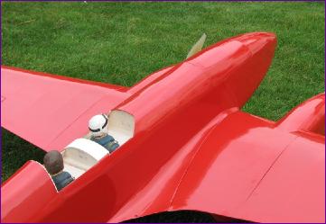
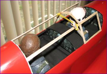
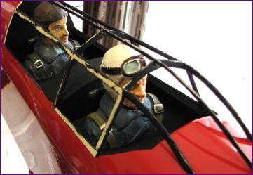
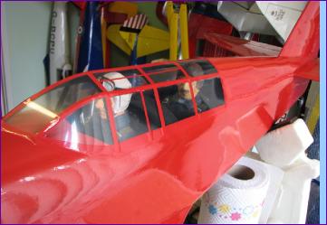
After a few displacement activities like running the motors up and finalising the battery stowage arrangements, there was little choice but to face up to one of those jobs which, for me at least, has a greater than average screw-up potential - the cockpit and canopy.
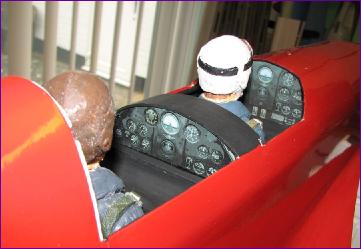
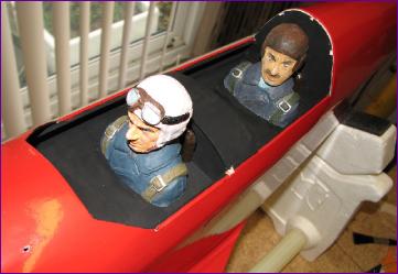
Interior finishing was kept simple with paper printed instrument panels, balsa seatbacks and matt black paint all round.
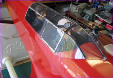
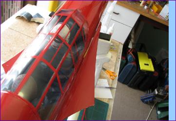
Last act of the month was to build and paint the frame. So far, so good, but it could take most of next month to psych myself up to do the glazing!
March 2012 (more on March) Glazing the cockpit involved much template cutting, dry fitting and trimming (more detail on the March diary page), but eventually the job was done.
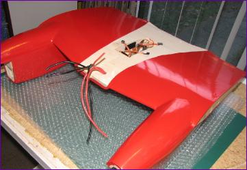
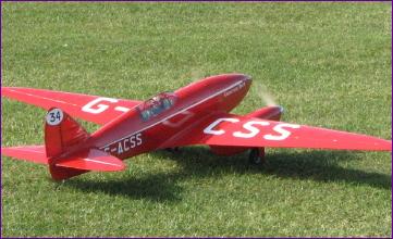
After the stress of glazing the cockpit, it came as quite a relief to apply the registration markings. These were supplied by Tim of Modelmarkings.com
With all now ready for a maiden flight, I woke up on the appointed morning suddenly worried whether the cg was really right! I found that my two different makes of 4s x 3000mah LiPos differed in weight by almost 2oz, so a bit of lead was added as a precaution.
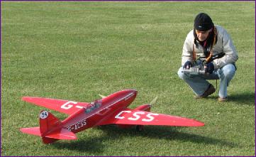
More nervous checks at the field, then there was nothing for it but to line her up and go. . .
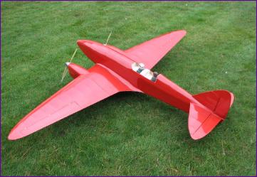
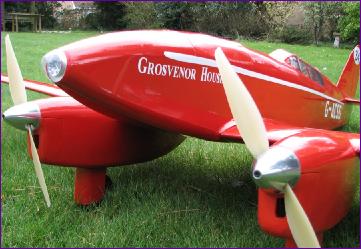
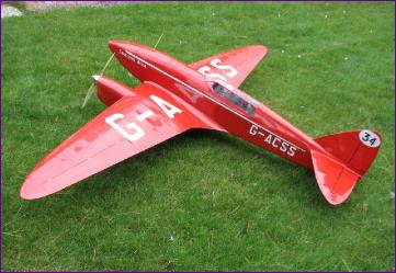
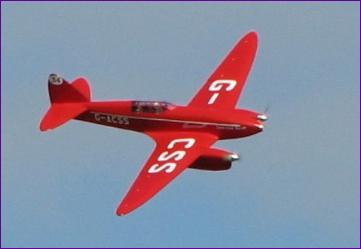
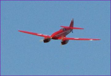
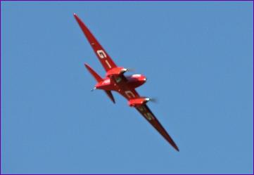
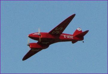
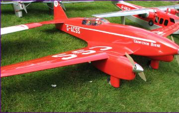
Of course, this is an Ivan Pettigrew design so, despite the liberties I had taken in eliminating the NACA cuffs, modifying the wing and tailplane outline etc., the model behaved impeccably. And of course, there are few planes more photogenic than Grosvenor House.
Truth to tell, these pictures were taken on the second flight. For the maiden, I prefer to have a video camera on the model just in case any post mortem investigation is necessary. Here is the video of the maiden flight.
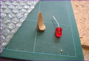
The only casualty of the first outing was the LED cluster forming the noselight. This was taken from a cheap torch and, after the maiden flight, only 3 of the 9 LEDs in the cluster were still working. The investigation and fix for this problem is covered in the March diary entry.
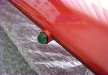
A tailwheel fairing and the nav lights were added as finishing touches.
One day the Comet might get some exhaust stubs and/or a pitot tube but for now, I'll just enjoy flying it for a while.
 Thanks to the modest dihedral angle, the 1/8in central spar can now be cut out in one piece and the 1/8in sq spruce strips have a more generous overlap
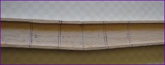
 The rear portion of the centre section ribs was added next, with a rear spar 'egg box' joined to the ribs to provide a hinge line for the flaps.
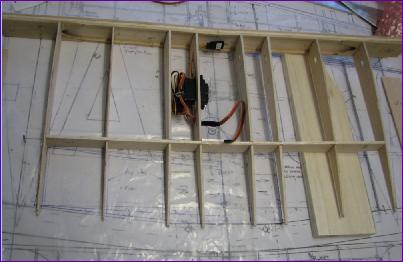

 The one-piece rudder and tailwheel actuating rod simplifies things in one way, but it does have to be installed fairly early on in the proceedings. A ball link was threaded onto the wire during the bending process.