D. H. Dragon Rapide Project Diary by Trevor Hewson
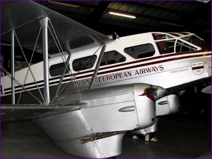
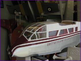
Having enjoyed the Sealand project so much, I didn't take too much persuading to tackle another of Ivan Pettigrew's designs. Ivan has drawn up plans for a good range of aircraft, both military and civilian (see http://www.ivansplans.com/ ) and, after browsing through the collection, I settled on the Rapide. I am a Friend of the Imperial War Museum at Duxford in Cambridgeshire and there are two Rapides that give pleasure flights during most of their events throughout the Summer season. Initially, I had planned to base my model on one of the Duxford Rapides but, being out of season, they were stored away for the Winter and so it wasn't possible to arrange a photo session. As luck would have it, I then found out about a lovely example (pictured above) in our local aviation museum in Bournemouth. Unfortunately, the news item which brought it to my attention was announcing the imminent closure of the museum so a visit was hastily arranged. The staff were most helpful and so I was able to get lots of photographs of G-AGSH, both inside and out. You can see some more photographs from this visit here. I have followed a similar build diary format to that used in the Sealand Project Diary, trying to keep each month's diary entry fairly brief, with 'More..' links which you can follow for more pictures and/or explanations if you are interested in that stage of construction. |
||
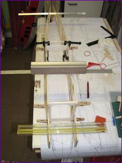
Once all the tail surfaces were built, hinge slots were cut and the whole lot dry assembled so that the linkages and servo positions could be sorted out.
|
||
February 2008 Little did I realise it but, even with all the ribs cut out, construction of the wing was only just beginning. The wing structure is complex, with several sub-spars, all of which require more notches to be cut in the ribs. As a result, progress during February did not merit a single photograph although, by the end of the month, the top wing was at last beginning to come together. |
||
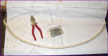 Having got a basic fuselage framework, I moved onto the tail surfaces, opting to form the leading edge by laminating five layers of 1.5mm balsa.
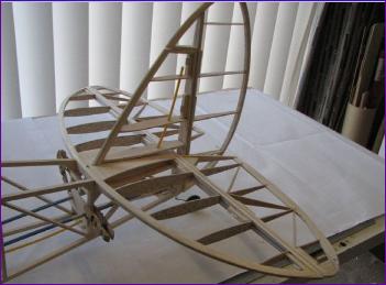 At this point the fuselage was put aside and the last few days of January were spent cutting out what seemed like an unending supply of wing ribs.
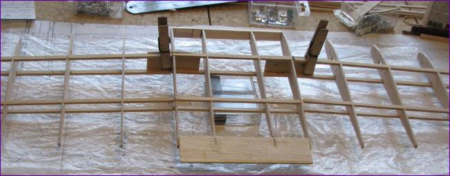
Having done so much preparatory work on the wings in February, it was gratifying at last to see a more or less complete upper wing ready to be fitted to the fuselage.
I opted for single, centrally mounted, aileron servos to reduce the amount of wiring involved. It is relatively easy to arrange for plenty of aileron differential and this is hardly the sort of model where a flapperon mix is going to be of much use!
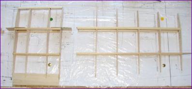
The lower wing is a more complex build than the top one, mainly because of the four dihedral breaks. This first picture shows the short centre section and an inner panel. Here are the three centre panels dry fitted together showing the anhedral:
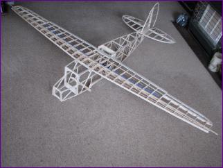
For ease of handling, I delayed attaching the lower wing outer panels until the nacelles were complete, but I couldn't resist dry fitting it all together, just to see the shape of the Rapide beginning to emerge.
|
||
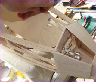
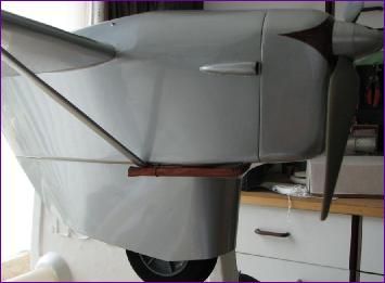
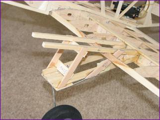 The other complication on the lower wing is of course the engine nacelles, which have to carry the undercarriage too. This picture gives some idea of how they attach to the wing.
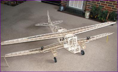
Once the leading edge sheeting and basic nacelle framework were in place, the firewall position could be worked out and the undercarriage trousers built up. Then it was time to sort out the motor mountings.
|
||
|
||
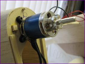 The motors eventually selected are Keda KD2217-20T. These are slightly longer than the Hyperion motors used in the Sealand and come with this rather nice alloy propeller mount which screws to the motor case.
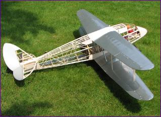
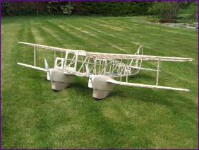 With the motors in position, the cowlings could be built and then at last the three sections of the lower wing were joined and the aileron snakes and bellcranks fitted. Once again, at the end of the month I was able to assemble the model and see some real progress.
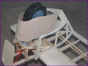
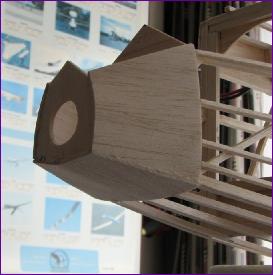
Time now to tackle the nose, including the issues of battery stowage and that all-important landing light. The first stage, shown in the picture on the right, went smoothly enough but I managed to make a real mess of the first noseblock.
|
||
 However, by then, I had worked out a solution to the problem of inserting and removing the halogen lamp which I had selected for the landing light. This involved making the battery tray double as an insertion tool for the light as you can see here.
|
||
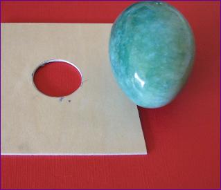 To mould the lens, it was a question of making a suitable sized hole in a piece of ply then looking around the house for something the right sort of shape. I eventually settled on this decorative agate egg, which produced a useable lens at the first attempt.
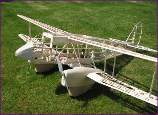 With a basic cockpit framework added, the model was now beginning to show the character of the full size.
|
||
 Time at last to start covering up that lovely airframe. However, before covering the outside of the fuselage, there was a lot to be done inside.
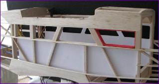 The picture on the left shows the interior of the cabin being 'dry lined' with cardboard, and the window frames being built up and lined. It took a lot of head scratching to work out how the floor, ceiling and front & rear walls could be fitted so that the model could still be easily assembled and the radio gear remain accessible.
June 2008 (More on June)
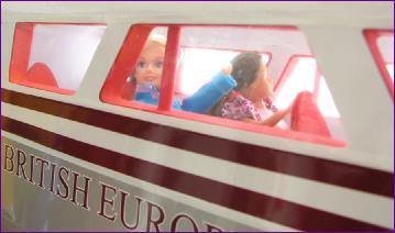
The instrument panel was also based on a photograph of the real thing, but required a lot of re-touching both because of the odd camera angle (photographed through the cabin doorway) and also because parts of it were obscured by the control column. The pilot was duly installed and the cockpit windows lined with white trim.
The cabin windows posed another challenge. These were cut from acetate sheet as usual but the problems started when trying to apply the white Profilm to frame them. After damaging the first set of windows with the heat from the covering iron, I finally accepted that I had to frame them with trim and accept a few more joint lines. Fortunately the colour match is quite good.
Mindful of the very nose-up ground attitude of the Rapide and the ever-present hazard of tip stalling those tapered wings, I made sure to get the tail up as soon as the model was rolling. Then, as soon as I eased off the forward pressure on the elevator stick, we were flying.
Thanks to Dave Blandford, you can see a short video of the maiden takeoff and landing via the 'Video Clip' buttons at the top and bottom of this page. |
||
 Whilst the basic colour scheme of G-AGSH is a fairly straightforward silver and white affair, the Burgundy trim caused me a bit of a headache. I found some trimstripe of a suitable colour but couldn't find any sheet trim to do the anti-glare panel etc. Then of course, there was the question of the lettering. In the end, I turned to a local signwriting firm for a bit of help. You can read more about it in this
 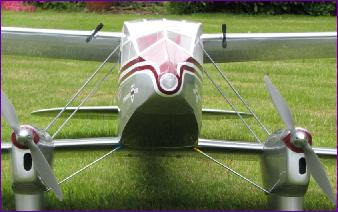 Fiddling my way around the noselight also proved a bit of a challenge, but I was well pleased with the finished result. You can also just make out in this picture the red curtain dividing the cabin from the cockpit. This serves to disguise a slight disconuity of ceiling height and also gives a bit more 'knuckle room' when installing and connecting the battery.
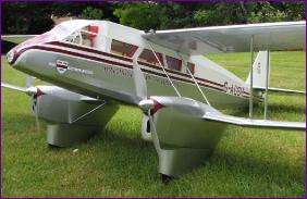 Although there was still a fair bit of detailed finishing to do, all of a sudden, the Rapide was ready to fly and, since a calm interval in the British weather obligingly presented itself, there were no excuses left.
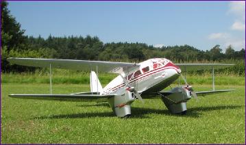
 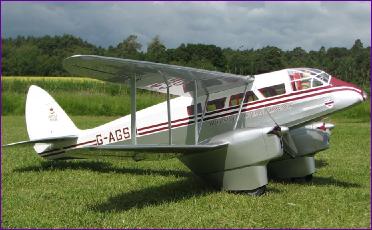 So it was off to the flying field for a few more pictures (and a not entirely convincing range check - still haven't got to the bottom of that one), then it was time to go.
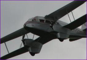 I am delighted to report that the model handles beautifully. Admittedly, the conditions were perfect, but even the landings were straightforward - once I had appreciated that this model has a much lower sink rate on the glide than the average biplane! After all that agonising over powerplants, it was also pleasing to find that there is ample power in hand. I can't report on precise flight durations yet, but the early indications are that the 3s 3700mah battery is more than sufficient.
|
||||||||||||
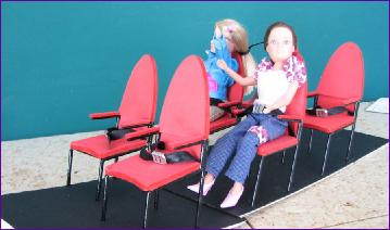
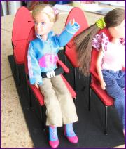 Then it was a case of fitting out the cabin. Seats were fabricated from aluminium tubing and upholstered with red Funky foam, to match the window surrounds. Finally a couple of likely looking passengers were secured in place and by the end of the month the model was ready to begin passenger carrying service.