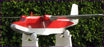
Sealand Project Diary by Trevor Hewson
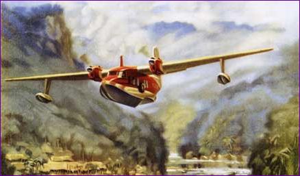
As the Winter of 2006 approached I felt the need to undertake a proper building project, especially after having something of an ARTF year (Piper Cub and Mig 3). But what to build? As a browse through my online log books will show, I already have too many models which don’t get enough flying so it would have to be something that would extend the flying opportunities. Remembering the fun of flying the Miss Hyperion off water, the idea of a flying boat of some sort arose. However, we really don’t have a regularly available aquatic site so, if the model was going to see some air time, it would have to be flyable off land too, so I started looking around for amphibious subects. The need for back-friendly easy rigging at the field ruled out biplanes but, to take full advantage of electric power, a twin engined subject had some attraction. It would be neat to say that my choice of the Sealand was inspired by finding the above poster for sale on eBay. However the reality is that, after a bit of web surfing, I alighted upon the plans of Canadian modeller Ivan Pettigrew and I eventually chose the Sealand from his extensive collection (at http://ivansplans.com/ ). This model spans just under 75in and Ivan’s prototype flew on 8 CP1700 NiCds at an AUW (without wheels) of 60oz. With a wing area of just under 700 sq ins, this model is very light at a loading of 12.6oz/sq ft. For once then, I could look forward to building a model without looking for opportunities to lighten it at every stage! Once the plan arrived (Ivan's service was very prompt), I ordered up a selection of wood from FliteHook, cleared some space in the workshop and made a start. Throughout this project, I have reported progress by e-mail, with accompanying pictures, to a few fellow modellers, seeking their advice and discussing various issues as they arose. During this time, one of them (Mike Roach) took over the care and maintenance of the Christchurch and District Model Flying Club website and promptly launched a 'Projects' section where he began posting pictures of the Sealand along with extracts from my e-mail messages. This worked so well that I have shamelessly cribbed the idea for what follows. I have tried to keep each diary entry fairly brief, but you will see several 'More..' links which you can follow for more pictures and/or explanations if you are interested in that stage of construction. |
||
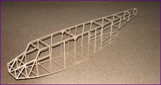
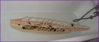
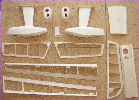
At this stage I opted to defer putting the upper bulkheads in place so that the model would sit inverted on the building board whilst I tackled the hull. Although I wanted to follow Ivan’s lightweight construction approach, I must confess that I did add the two X braces you see in the picture below to reduce the risk of distorting or damaging the structure whilst working on it. |
||
|
||
|
||||||||
|
||||||||||||||
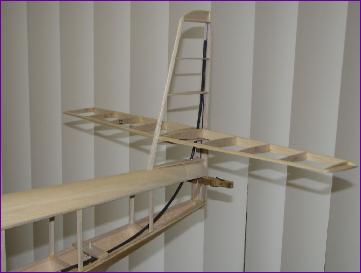
 Again, aileron servo, linkages and hinges were sorted out early, before applying the leading edge sheeting. As in the flotation test, my old NiCd batteries were pressed into service as weights.
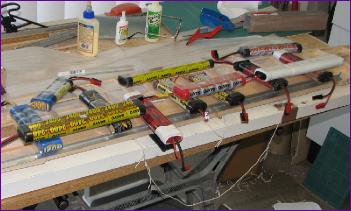
|
||||||
|
||||||
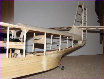
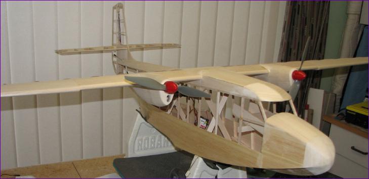
Sorry I forgot to fit the tip floats for this picture! By the end of the month, I had got the wiring done, control surfaces hinged and working and was beginning to get that pre-maiden flight feeling.... |
||||
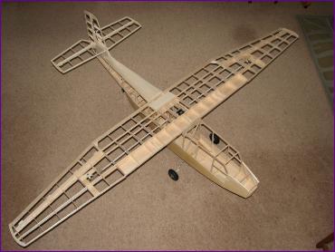
... and it flies! The model handles extremely well and I can easily get two 15min flights out of one 3700mah 3s LiPo battery. Being so lightly loaded though, it looks best when flown in fairly calm weather. After a while, I felt that it would be nice to see the model in 'wheels up' mode, so it was a case of waiting for a suitable occasion... |
||||
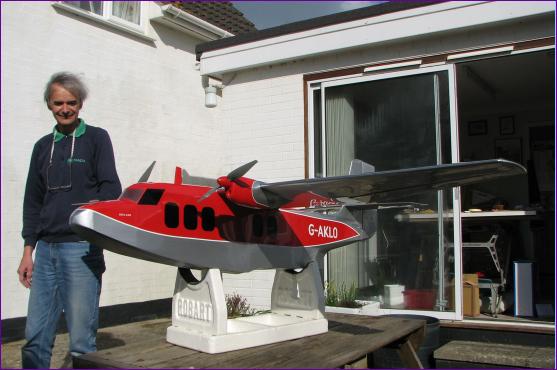 Having got the airframe covered, I then set about applying the white pinstripes and added some stickers to simulate the side windows. This transformed the model yet again and, if I look a little self satisfied in this photo (taken on an inspection visit by Mike Roach), then I can only say that this is what makes these projects worthwhile.
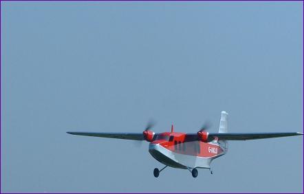
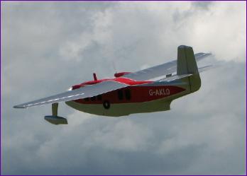
After two wet months, I finally got to the flying field on a day when the wind was light and plucked up the courage to fly the model without wheels and with the tip floats. It looked really good and, to my relief, the air was perfectly smooth on the landing approach and the tip floats never even touched the ground.
The only problem now was that, because of the very wide fuselage, I was finding difficulty in recruiting volunteers to hand launch the model, so the wheels went back on for a while. Sooner or later though, something had to be done. . . |
||
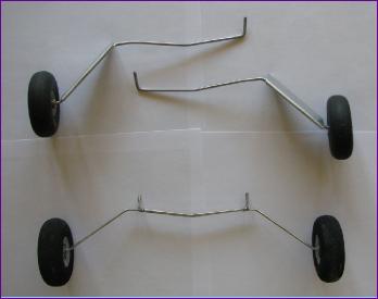
The original undercarriage wires on the Sealand turned out to be a bit thin and 'twangy' so were replaced fairly early on with a heavier guage wire. When I came across the original u/c wires during a tidy-up, the idea occurred of trying a drop off undercart, so that I could fly the model 'wheels-up' without the need for a hand launch.
The picture shows the Mk. II fixed (but removeable!) undercarriage legs at the top, and below, the original legs soldered together to make a drop-off u/c. Whilst the first trials of this showed promise, the u/c did not always drop cleanly and, having come close to crashing the model during increasingly violent manouevres in an attempt to shake the wheels off, this approach was eventually abandoned. More beautiful wheels-up pictures did though convince me that I didn't want to revert to the fixed u/c option.
Recently, I have found that such is the power of these little brushless motors that the model will generally take off from grass without the aid of wheels at all - so now both sets of wheels are surplus to requirements! |
||
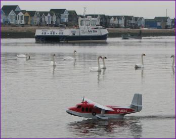
Over the Winter of 2007/08 I had hoped to get the opportunity to fly the Sealand from floodwater but, one way or another, it never quite happened. Early in May, clubmate Mike Roach finished his Catalina (another Ivan Pettigrew design) and persuaded me that we should don waders and stride out ot a sandbank in Christchurch harbour.
This proved to be a very successful outing - click on the above link for more watery pictures. Steering using differential throttles (coupled to the rudder stick) was very powerful and the tip float retention mechanism worked well. I was also delighted to find that the inside of the Sealand remained completely dry.
All in all, a very satisfactory way to round off the Sealand's first year of flying.
|
||