During a spell of rather disppointing weather in the so-called Summer of 2016, I found my thoughts turning to the prospect of the coming Winter build. A quick scan of my overcrowded hangar showed that I am very well stocked for flat field flying sessions but, with the exception of the recent (and very successful) Zulu and Hammer, the soaring fleet was definitely showing its age. In fact, leaving aside those two newcomers, the rest of the soarers have an average age of 25!
The only scale glider I've ever built was a 1/6 scale Wik Salto back in 1987. Whilst it looked the part and flew quite well, I never really gelled with it and sold it on some 9 years later. Since then, I have seen many 1/4 scale models flying off the slope and can't help but admire their grace in the sky but, as I know from the T61 Motor Falke, they do take up a lot of room, both in the Hangar and in the car.
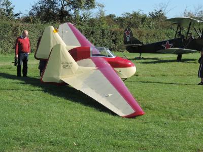
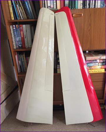
So I started looking for 1/5 scale gliders. Unfortunately, the choice is limited and all the time 'those that know' kept on saying that 1/4 scale models fly better. Whilst pondering this conundrum, I suddenly remembered seeing a very spirited aerobatic display at an Old Warden airshow from a recently restored AV36. I did find the aircraft very characterful and, with the twin fin arrangement, it clearly lends itself to a three-part wing. That, combined with the minimal fuselage pod, should go a long way to easing the storage and transport issues. At 1/4 scale the span comes out to about 135", just a little smaller than the usual standard class glider.
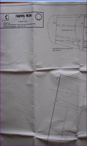
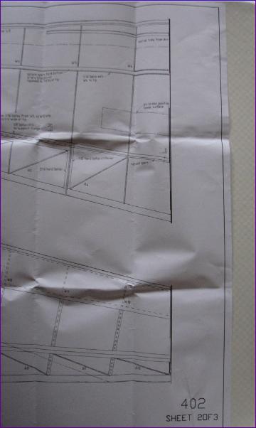
A bit more research revealed that there was indeed a plan available, albeit a rather old design, by Gordon Waite, so this was duly ordered. First impressions were good - there were several details on the plan that indicated that it was by an experienced designer and the building techniques were generally ones I was comfortable with. Further inspection though revealed some more worrying features. Firstly the title panel of the plan bears the legend Fauvel VA36 rather than AV36. More disturbingly, the build notes for the wings refer to the ribs by R numbers but on the plan they are labelled W1 to W10 - or at least they are on the right hand panel. On the left hand panel we have W4-W13! What's more the two panels don't appear to be the same shape. Eventually the penny dropped - the drawing has been truncated on the right hand side. It doesn't run off the paper, it is just as if the plotter stopped traversing and drew the last eight inches or so of the drawing in the form of one thick black line, see pics below.
I'll spare you the details of the mini-saga that unfolded over the next month or so. Suffice it to say, that I now have three identical copies of sheet 2 of this plan. To be fair to MyTimeMedia, after these three failed attempts to provide the complete drawing they gave me a full refund and pledged to keep trying to get to the bottom of the problem. I've heard no more since and, having accepted the refund, I don't feel I should chase them any more.
Of course, reconstructing the complete outline of an outer wing panel from the two partial drawings is no problem. The difficulty is that the drawing of the right hand panel shows the inboard end sheeted in and I'm sure that all the internal detail on the wing joining arrangements etc. is on the missing inboard end of the left hand panel.
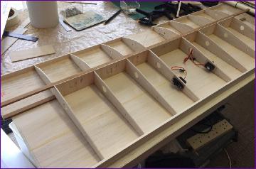
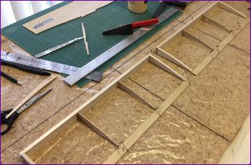
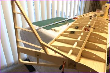
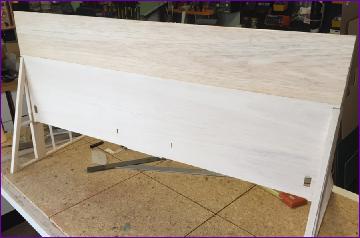
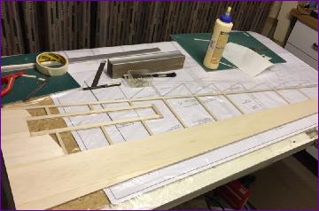
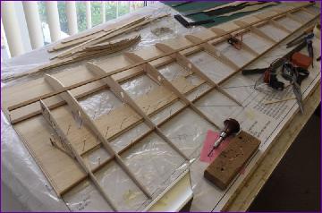
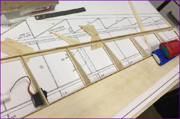
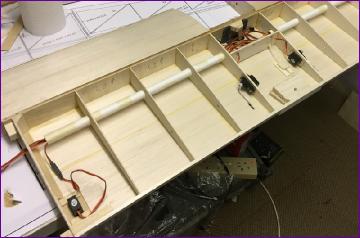
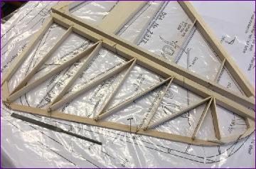
September 2016 Oddly, all this frustration over the plan only strengthened my resolve to build this model so, after a quick inventory check and a few internet orders for servos etc., I rolled out the plan for the central wing panel. This panel is completely sheeted and the section is flat bottomed from leading edge to elevator hinge line so, for once, I felt inclined to build the framework over the lower skin.
Being an old plan, central servos and bellcranks are shown throughout. I opted instead for eight Corona DS-939MG metal geared 12g servos; two each for elevators, rudders, ailerons and flaps.
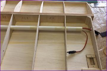
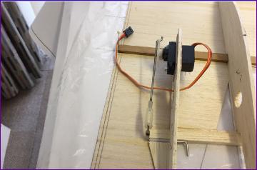
Here you can see the first servo pair (elevators) fitted, using my preferred 'through the rib' mounting arrangement.
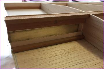
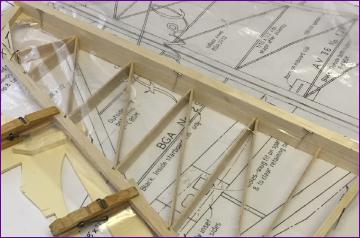
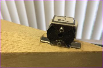
The plan shows the wing panels joined by piano wire in brass tubes. However I had some brass box / steel blade to hand so opted to use that.
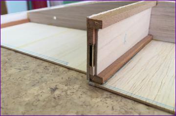
For the rear joiner though, I stuck with the piano wire and brass tube approach. Note that the ply and spruce box around the tube extends beyond the rib. This serves as a locator for the fin and, by virtue of the end of the box bearing on the root rib of the outer panel, provides crush protection for the fin too.
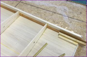
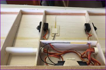
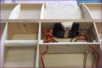
The next pair of servos to be fitted were for the rudders. Mounting them in the underside skin seemed the simplest way to do it but I'm still not sure about having that much servo sticking out into the airflow so this arrangement is still subject to review.
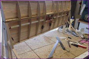
Last job of the month was to fit the wiring tubes and sort out the receiver mounting. For an 8-servo setup, it doesn't look like too bad a bird's nest!
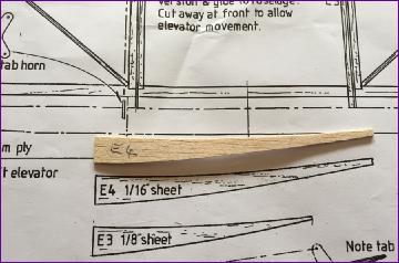
October 2016 The elevators are shown with spruce trailing edges. However I didn't fancy my chances of sanding the spruce precisely to section beforehand and, since the general construction of the elevators is so light, there was no way I'd be able to shape it afterwards. So I opted to use a lamination of 1/32in ply and 3/32in balsa instead.
The elevators are heavily reflexed and are shown here upside down.
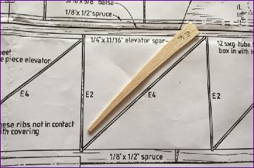
At this point I encountered an error on the plan: The elevators have diagonal ribs and, as you can see in the next pair of pics, as drawn, the diagonal ribs are too short. Fortunately I discovered this before cutting out all six of them!
This problem was easily sorted though, and the elevators were soon finished. However, with all that reflex, I can't say that I look forward to the challenge of covering them!
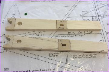
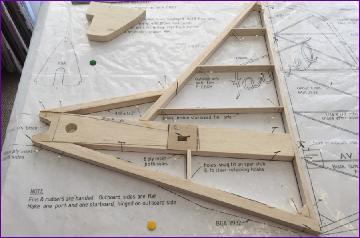
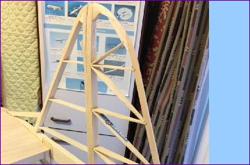
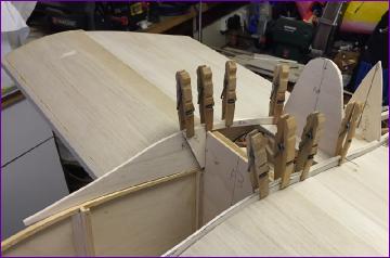
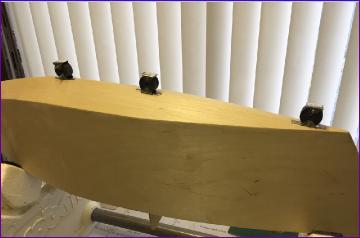
Attention then turned to the fins. These are essentially built from 1/2in balsa, the key component being the central piece which locates onto the outboard end of the wing centre section.
Upon seeing these pictures, a fellow modeller remarked that I seem to be building a garden bench rather than a flying machine! I have to concede that he has a point.
Having reached this point by the middle of the month, progress rather ground to a halt due to family commitments and other demands of life in general. Mind you, this did include getting out to take advantage of some nice autumnal flying weather, so I'm not complaining.
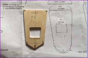
Finally, in the last few days of the month, I got back into the workshop and began work on the fuselage. Some 3/16sq basswood longerons were persuaded to follow the contours of the 1/16in ply fuselage sides and some formers were cut out of 1/8in ply.
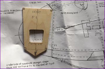
Unfortunately, another plan error came to light here, as illustrated by the two photos below. You can see that I had to make F1 considerably less deep in order for it to match up with the side view of the fuselage. This looks like a simple drafting error when the plan was originally drawn up but does seem to confirm, as is unfortunately the case with most published plans, that no model was ever built from the plans before they were submitted for publication.
Although the fuselage sides should be good and strong, they do feel rather stiff so I am aniticipating quite a battle when it comes to pulling them together at the front and rear. More on this no doubt next month.
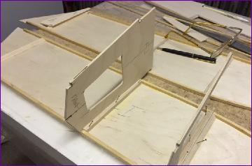
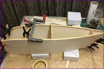
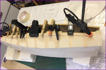
November 2016 (more on November) Once the spruce longerons had been glued to the sides (a bit of soaking helped them take up the curves), the formers were notched appropriately and a series of dry fittings commenced. The fuselage sides are nominally parallel in plan view between F2 and F3 so it made sense to join the fuselage on these. I decided to pre-fit some 3/16 square balsa and triangle strip to make sure the formers located properly, then glued them in place, eyeing the assembly up from all directions.
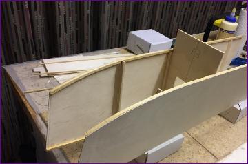
Then it was time for the big squeeze! There are more details on the November diary page but, after lots of preparation and rehearsals, it went surprisingly well. F2 is heavily cut away to make room for the pilot so a temporary strut was clamped across the top of the aperture to avoid distorting things as the nose was pulled in.
The picture on the right shows a trial fit of the keel (to be laminated in situ from three pieces of 1/8in sq. spruce), just to show off how straight it all turned out.
I've often thought that I ought to invest in a building jig but, with a shape like this, I'm not sure how much it would have helped.
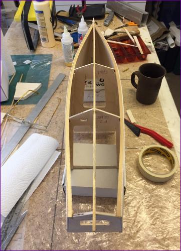
Final fitting of the keel was deferred so that the fuselage was easier to support upright while sorting out the wing seating. I was going to criticise the plan again here because, although there are two fixing dowels shown locating the spar against F2 (hidden behind the pilot in this picture), there is nothing shown for fixing the trailing edge.
I went ahead and fitted a standard 6mm nylon bolt and T-nut arrangement but later in the month mangaged to obtain a copy of Gordon Waite's article which accompanied the plan's publication. In that, the instruction is quite clear that the wing centre section is to be glued in place on the fuselage. Fair enough. On balance though, I think I'm happier with it being removeable.
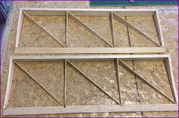
Next it was time to make a start on the outer wing panels. These are very lightly built for a slope soarer - another thing which made more sense after reading Gordon's article and realising that he designed the model for flying off the flat rather than for the rougher ground usually encountered at the slope.
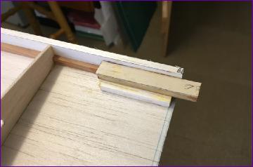
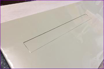
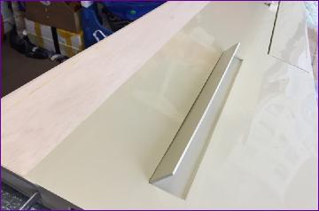
Construction starts by building up the lower wing skin. The position of the flaps/airbrakes (I can't decide which to call them!) is indicated on the plan but no details are given since the prototype model wasn't so equipped.
This meant that I was on my own when it came to working out how to make, mount and operate the flaps. It's not that they are particularly complicated (although they do taper slightly and nothing is actually square), but the apertures and hinges do have to be built in at a fairly early stage. Hopefully the photos give you an idea of how I approached it. There are more pics on the separate November diary page.
Before going much further, I was keen to sort out the join between the wing panels. The article says "Install the wing joiner tubes in the centre section and outer panels, ensuring accurate line up and dihedral". So, not a lot of help there, and what's more, I couldn't find anything about the dihedral angle on the plan. It's possible of course that it is on the missing section.
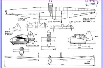
I found this three-view on the web which shows a dihedral angle of 2.5 degrees. However, no matter how much I checked my calculations, when I rigged the wing joiners at this angle the dihedral looked too little. In desparation I measured the angle on the three view itself and it came out an more like 4 degrees! Eventually I realised that the discrepancy is because the angle quoted on the drawing relates to a line drawn (or rather not drawn!) from the wing tip to the middle of the rather thick root rib whereas the angle I was looking for is at the dihedral break in the underside of the wing.
Mystery solved, I then set about making up ply boxes to accommodate the steel joiner bades, which would fit between the main spars and up against a ply shear web. Unfortunately, I was focussed so hard on this job over several days that I quite forgot to take any pictures.
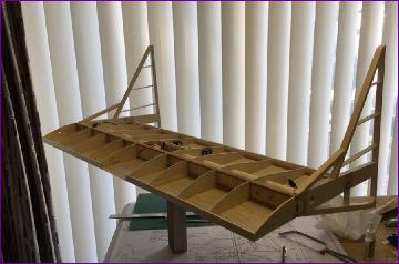
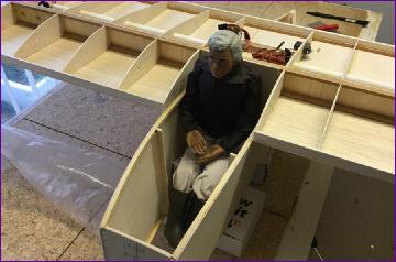
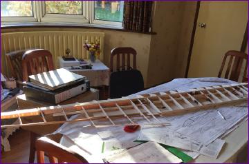
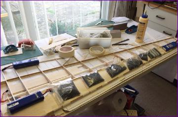
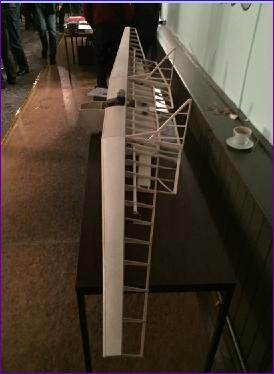
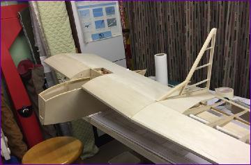
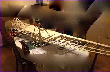
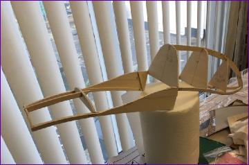
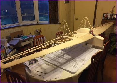
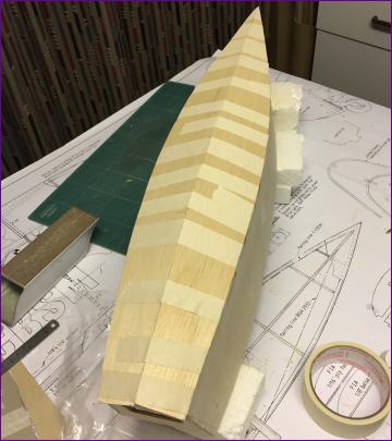
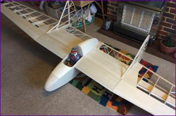
Anyway, by the end of the month, the panels could be plugged together, and the full scale of this machine could be appreciated.
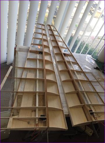
The next stage is to begin sheeting in the top surfaces of the wings which, in the case of the outer panels, is a particularly critical step since it will lock in the washout which could have a big impact on how this beast performs in the air.
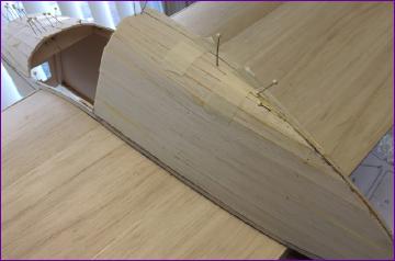
December 2016 Once the leading edge upper skins had been butt jointed together and the various ribs built up or sanded back, the wing panels were propped up with the recommended washout and the sheeting glued in position. A combination of weights, masking tape and cyano tacking was used to hold it in place.
I took the model along to the club meeting early in the month and this was the first time I'd assembled it with the sheeting in place. The steel blade wing joiners were very stiff and it was clear that assembly and de-rigging the model without damage was only possible by grasping the spars of the centre section and the leading edge D box of the outer panel.
There followed many more partial trial assembly sessions in order to fettle the joins between the wing panels and, in between sessions, the steel blades were attacked with the Dremel and the fit gradually became easier. I don't want the joiners to be too loose though, since I am hoping to avoid the need for a mechanism to lock the panels together, other than perhaps a couple of small magnets.
The next task was to complete the sheeting of the centre section - not forgetting to install the rudder servos and elevator pushrods first of course.
Apart from the addition of cap strips etc., that is all I managed to get done in December before Christmas family commitments took over.
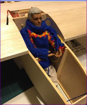
The pilot did get to try on a new jumper though. A little on the large side, perhaps?
January 2017(more on January) I've taken nearly 50 photos this month so that ought to mean that there's plenty of progress to report. To avoid this page becoming totally unweildy, a lot of the photos have been put in a dedicated January diary page so do check this out for more details on any of the construction phases - just click on the 'more on January' link above.
First up were the ailerons. These are very light but quite complex structures. There is reflex built into the section, cap strips on top but not underneath and diagonal ribs which reduce to something like 1/16in by 1/16in in section towards the trailing edge so very susceptible to handling damage.
The ailerons are also very long, taper in all directions and have to follow the washout in the wing so, since I want to hinge them with the covering, keeping the hinge line dead straight was really important.
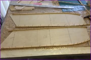
Next came the rudders. These are a bit unusual, being flat on the outboard sides. This means that the right hand rudder can be built flat on the plan as shown here. The ribs are from 1/16" balsa so I cut them from a 1/2" wide strip of wood with a view to shaping them later.
However, before shaping the ribs, the rudder was flipped over, protected by a sheet of polythene and used as a template to construct the frame of the left rudder, as shown in the pic below.
The rudders were then temporarily taped to their respective finposts and carved and sanded to shape.
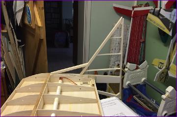
After all this 'fine structure' work, it seemed like a good time to put it all together again. (sorry about the clumsy attempt to blur the distracting background clutter!)
The steel blade/brass box joiner system that I'm using to join the wing panels was very tight and it was only possible to assemble and dismantle the model by grasping through the structure in a way that won't be possible once it's covered. So, between each of these trial assemblies, I was working on abrading the steel joiners to ease the fit.
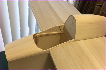
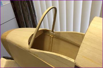
Attention now reverted back to the fuselage and, in particular the top section. This is clearly described in Gordon's article as a one piece, lift-off section. However, on looking at the plan, it seemed that the front and rear portions were joined together only by the acetate canopy. The photos of the prototype accompanying the article clearly show a shallower canopy fitted, enabling the upper sides of the fuselage to be continuous. Gordon acknowledges that his canopy was non-scale, and the plan has clearly been modified to show a more true to scale shape but at the expense of structural viability.
I decided to raise the side of the canopy about 1/4in which enabled me to build in small L-shaped pieces of ply to reinforce the join of the front and rear portions of the framework, as can be seen on the first of this sequence of four pictures. Once the planking was sanded down, I was quite pleased with the finished result.
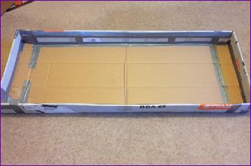
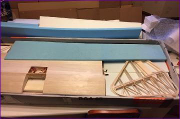
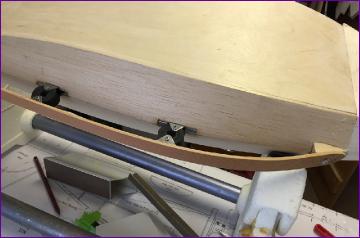
While shaping the leading edges and adding the wing tips (sorry, no pics), I found myself pondering the looming issues of transport and storage, and decided that a custom box would be a good idea. A trip to the local tool hire emporium yielded a selection of suitablty large, but entirely the wrong shape, boxes and there then followed the best part of three days work remodelling them into something more appropriate.
So, as another month draws to a close, all that remains in terms of construction is the fuselage underside, undercarriage and noseblock. And of course the dreaded canopy!.
I have though bought the covering so I'm in a good position to put off the canopy for a little while yet!
Don't forget, more details and more pictures are on the January Diary Page.
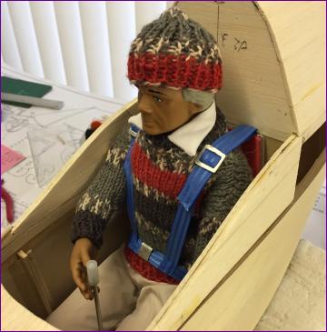
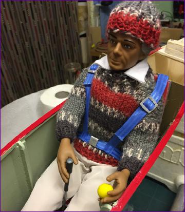
February 2017 The eagle-eyed amongst you might just have spotted in that last photo that the pilot has a new outfit. It only seemed right that this should be complemented by a seat and harness - and he even got a joystick. Instruments may come later.
Back to the construction, and the underside of the fuselage. The plan shows this as 1/16in ply but there's quite a bend on the panels so, since they will be protected by a spruce skid, I decided to use some firm 3/32in balsa. The first piece could be clamped to the keel while the glue dried but the second piece had to rely entirely on masking tape.
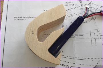
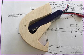
Next up was the noseblock. A trial balance indicated that, even with the biggest LiPo battery that I could sensibly fit, the model was going to need noseweight. So, before fitting the outer laminations of the noseblock, I fretted out the inner laminations to provide options for battery and lead stowage.
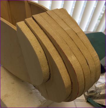
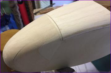
The remaining laminations were then fitted before fitting the whole thing to the fuselage and carving and sanding to shape. Once happy with the shape, the noseblock was given a couple of coats of sanding sealer and re-sanded.
During this process, the joint between the fuselage top section was fettled and a dowel fixing peg inserted in the front. The rear of the removable top section then attaches to the trailing edge of the wing with magnets.
While I was doing all this, a helpful clubmate was fashioning some metal brackets to fit the undercarriage skid. The shock absorbing rubber mounting bushes are simulated on the model by tap washers bolted into the metal fittings which are in turn epoxied to the underside of the fuselage and to the spruce skid.
The skid itself has quite a bend on it so this was pre-formed by brushing water onto it while it was clamped in a vice. I was quite pleased with how this all worked out but it remains to be seen whether it will be vulnerable in a slightly crosswind landing.
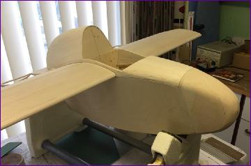
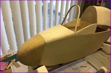
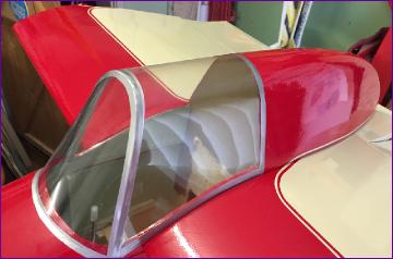
One final fully assembled shot before starting covering - and then I thought that, before giving the workshop a good clean, it might be as well to laminate up the hoop former that divides the windshield from the main section of the cockpit canopy.
After all this, it was three weeks into February before I finally got the covering iron out. So, is a maiden flight in March still a possibility?
Your guess is as good as mine - watch this space!!
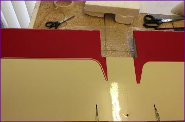
March 2017 (more on March) For once, I did remember to take a few pictures during the covering stage this time but, since this page is already getting far too long, most of them have been relegated to the separate March diary entry. The basic colour scheme of the Shuttleworth example is quite simple.
The flaps are somewhat simplified compared to the full size. What they will do to the pitch trim of the aircraft is just one of the unknowns to be addressed on the maiden flight.
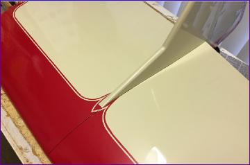
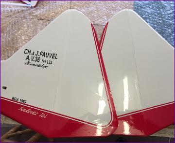
I was surprised just how much the addition of a simple coach stripe enhanced the appearance, although it did get a bit fiddly around the fins.
I managed to put off the dreaded canopy for a day or so by tackling the installation of the battery and uBEC (see March page for pics). Eventually though it had to be done. The acetate used was from a discarded box from one of the grandchildren's toys and, try as I might, I couldn't get the silver trim around the windscreen section to lie down neatly.
So, one way or another, I'm not too satisfied with the canopy. The full size has been fitted with what looks like a re-purposed moulded job, so maybe I might re-visit this bit of the model at a later date.
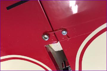
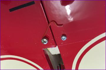
In contrast, I was quite please with the last 'engineering' job, which was to fashion a crude wing retainer from a paperclip and a couple of screws.
Tim Calvert (ModelMarkings.com) supplied the decals which really help to break up the expanse of cream covering on the fins.
With a joystick and an airbrake lever to hang on to, the pilot looks all set to go.
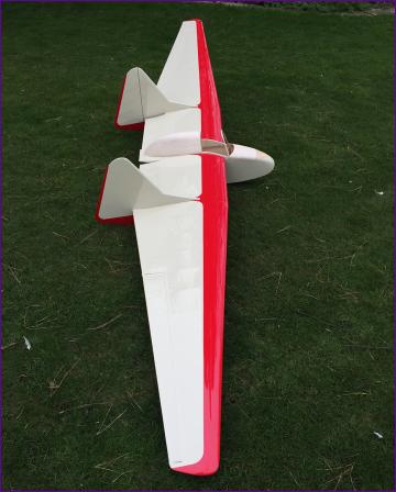
After an hour or two programming the transmitter, a careful check of the cg and one last photo shoot in the garden, there was nothing to do but pack the model away and await a weather window for the maiden flight.
As it happens, I didn't have too long to wait. The story of the first outing is captured pretty well in the video at the bottom of the page, kindly shot by a fellow flyer.
As you can see, the first attempt quickly revealed that the elevator trim was way out, full up elevator still proving insufficient to arrest the descent. After suitable adjustment to the linkages, yet more up trim was dialled in during the second flight, which was mostly spent trying to gain enough height to try the brakes. These induced a pitch up response so some down elevator compensation was dialled in - followed by more. And yet more!
The first attempt to start a landing approach was aborted when I found that the ailerons became ineffective when the brakes were deployed. On the second approach the brakes were pulled in whenever aileron correction was needed which was just about manageable but, on finals, I found that the elevator stick was fully forward and the nose still wouldn't come down. As a result, the final descent was effectively flown using the throttle (brake) stick in lieu of elevator - made more awkward by the fact that I had to pull back to come down - that's my excuse for the untidy arrival!
Afterwards of course, I remembered that I had a higher rates setting available which, had I used it, would probably have given me a bit more elevator and aileron control under braking. Just one of many lessons learned for next time!
Overall though, I was well pleased with this first foray. Bringing the model home intact was enough to chalk it up as a success but it sat well in the air, semed very stable and controllable and, in spite of the drag that must have been generated by the heavily reflexed elevator, coped well with what was pretty weak lift.
I have now made a few adjustments, including removal of a bit of lead from the nose in an attempt to improve the elevator response. I've also taken out nearly all of the upward aileron movement which I had coupled to the brakes since I suspect this may have been responsible for most of the upward pitching under braking.
Footnote, May 2017: With the control throws and mixes now fairly well tuned up, I'm pleased to report that the AV36 handles very well. In particular, it is very secure on the brakes which, with the addition of the outward moving rudders, are very effective. Because the low wing loading limits penetration on breezier days, I've also added the facility to carry up to 15oz of ballast. Details here. A video of the first ballasted flight can be found on the Video Clip page (link below).

 I took the model along to the club meeting early in the month and this was the first time I'd assembled it with the sheeting in place. The steel blade wing joiners were very stiff and it was clear that assembly and de-rigging the model without damage was only possible by grasping the spars of the centre section and the leading edge D box of the outer panel.
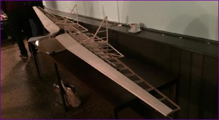
 Apart from the addition of cap strips etc., that is all I managed to get done in December before Christmas family commitments took over.
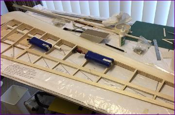
 So, as another month draws to a close, all that remains in terms of construction is the fuselage underside, undercarriage and noseblock. And of course the dreaded canopy!.
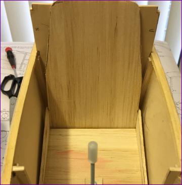
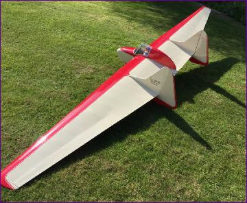 After an hour or two programming the transmitter, a careful check of the cg and one last photo shoot in the garden, there was nothing to do but pack the model away and await a weather window for the maiden flight.