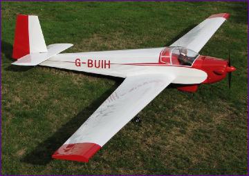
Slingsby T61 Motor Glider Project Diary by Trevor Hewson
The Astrohog build went somewhat more quickly than expected so, after a few months break, I found myself in November 2009 staring at an empty building board. I put off the difficult question of what to build next by embarking on long overdue refurbishment of a couple of faithful old models (the Lazy Bee and P38) and was given an Autogyro kit for Christmas (see Rotorshape). So that got me through to the beginning of February but the UK 2010 Winter was one of those that seemed like it would never end so, even at that late stage, I found myself looking around for the next major build. Eventually, I settled on the idea of a motor glider and before long found myself looking through Cliff Charlesworth's plans. The T61 seemed the right sort of size and so the plan, canopy and cowl were ordered and by the beginning of March I was in possession of a large pile of wood. I was somewhat alarmed to find that the wood weighed about 21lb which did make me question my 10 - 11lb all up weight target but then, I had over-ordered somewhat on the ply so, brushing aside such doubts, I set about clearing enough space on the bench to start. |
||
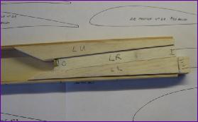
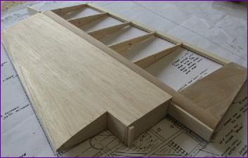
March 2010 (More on March) The spar itself was the obvious place to start. Before fitting the second facing to the inner section of the spars, the brass joiner boxes had to be fitted. I did this with two pairs of balsa wedges to set the forward sweep and dihedral angles.
By the end of the month I had begun construction of the right hand wing by gluing the leading edge portions of the ribs in place, followed by a balsa false leading edge.
|
||
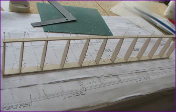
 Having made up the top and bottom spruce spars and cut out the ply facings, construction began. I used balsa spacers to try to manage the spar height so that it would match the ribs later (no rib cap strips are used so once again, there is no scope for fudging any height discrepancies).
  Once the spars were finished they were set aside to make way for a week of cutting out rib profiles. I cut all the ribs from 3/32 balsa on the basis that, where ply ribs are specified on the plan, I would apply thin doublers if necessary.
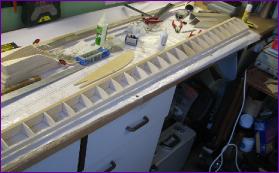
April 2010 (More on April)
The underside sheeting was applied in similar fashion then of course the process repeated for the other wing. The resulting D boxes are incredibly strong.
|
||
 Since the box spar is so torsionally rigid, I decided to fit the 1/64 leading edge sheeting before building the trailing edge section of the wing. The skins were cut out, sanded rough on the inside and smooth on the outside, then joined. What really took the time though was sanding the ribs and false leading edge to get everything lined up. I always thought that 1/16 balsa sheeting didn't allow much scope for sanding out any ripples but 1/64 ply doesn't allow anything at all!
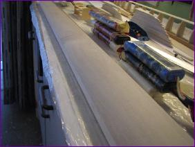 Thesheets were first glued to the spar and weighted down, then pulled down to attach to the ribs and false leading edge. Once all the tape is removed, the appearance of the ply sheeting is quite pleasing.
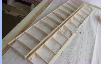
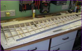 The process of setting out the trailing edge portion of the wing seemed unending - trimming the front ends to the correct angle, offering up the ribs to mark and notch them for sub spars, making holes for servo wiring tubes, and yet more notches and trimming to accommodate the spoiler. Eventually though, I could begin gluing them in place.
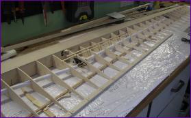 The plan shows a ply core slotted into the centre of the trailing edge of the ribs and balsa infill sections top and bottom. I didn't fancy that so instead inserted full depth 5mm balsa sections between the ribs, with a view to putting a ply skin on the top later.
 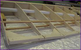 By the end of the month I had got the top and bottom rear spars in place and also tackled that strange crank in the trailing edge at rib 3.
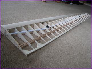 At this stage the right wing was set aside so that I could make a start on the left one - while I could still remember how I did it!
May 2010 (More on May)
The fixed portion was tackled first with the result you see here. This was actually a departure from the arrangement shown on the plan - see detailed May diary entry for more details. The aileron ribs were notched for the top and bottom spars (allowing for the subsequent facing) and the trailing edge was given the same treatment as the fixed section, with a selection of packing pieces used to set the washout.
|
||
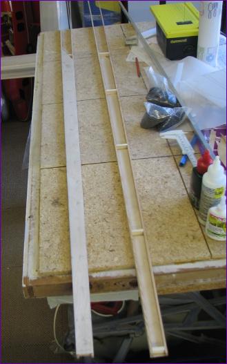
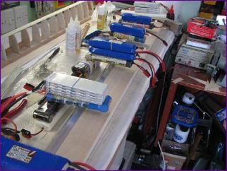
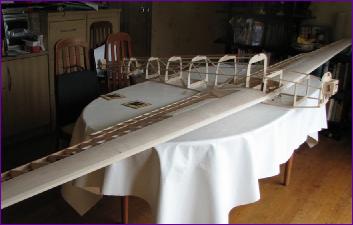
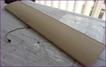
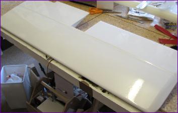
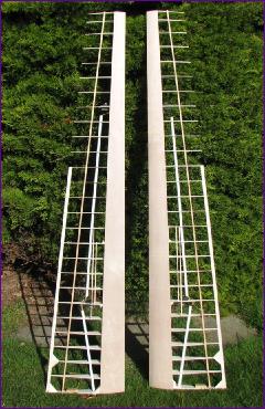 With the second wing brought up to the same stage, the problem of photographing the work drove me outside. An ominous sign of the storage problems that lie ahead, I fear!
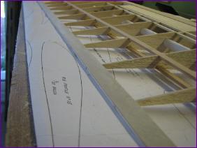 I was going to do the spoilers next and did make a start on one of them. However, this photo brought home to me just how vulnerable those aileron ribs are so I switched my attention to the trailing edge.
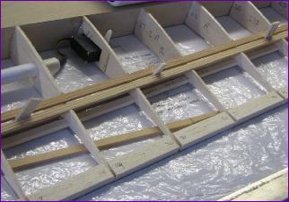 On the construction front, that was just about it for May. Partly because we went out to Canada for two weeks to attend the
 June 2010 (More on June)
July 2010 (more on July)
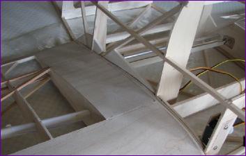
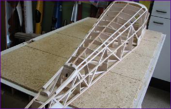
The formers were then joined using basswood for the lower longerons. The root ribs and top spine are just dry fitted in this picture.
Next came the upper longerons (basswood again) and the upper stringers. Spruce is specified for all longerons and stringers but I opted for balsa for the stringers, again in a quest to save a bit of weight at the tail end.
|
||
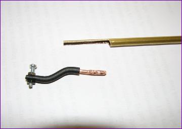
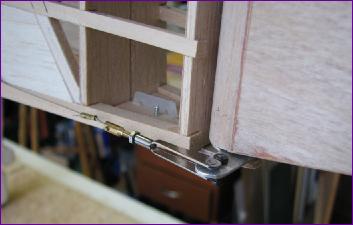
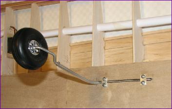
 Having completed the second aileron, the linkages were next. However, by opting for a semi concealed horn fixing, I made a bit of a meal of it but eventually got everything working okay.
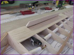 I then spent a good bit of time improving the alignment of the underside of the ribs - some needed building up a bit and then sanding back to get them flush with the leading edge sheeting and rear spar. With as much as possible done on the underside, the wing was turned over and it was back to the spoilers. Even more fiddling here (see detailed June entry for more details) but again a reasonable end result.
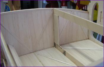
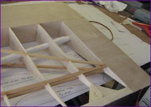 Other than that, there's not a lot more to say this month. The diagonal spars were fitted to the root area, and the root bay of the underside was sheeted in with 1/64in ply (the top will be left open until the wing fixing is sorted out) .
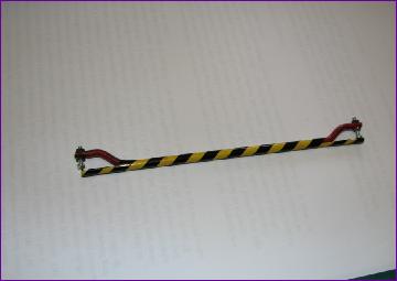
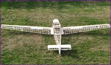
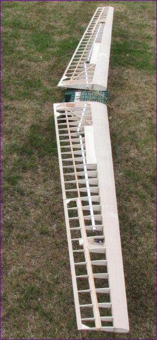 The last job of the month was to cut the wing joiner bar to length so that the wings could be joined together. It came as something of a relief to see the forward sweep and dihedral angles for the first time - they both look to be about right.
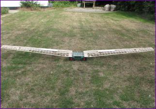 The wings, including ailerons, spoilers and servos weigh 1lb 8oz each at this stage. They still have no root ribs, leading edges and tips of course.
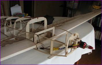
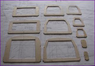 The formers are built up from a mixture of 1/16in ply and 1/16in balsa and hopefully represent a bit of a weight saving compared to the 4mm and 3mm ply specified on the plan.
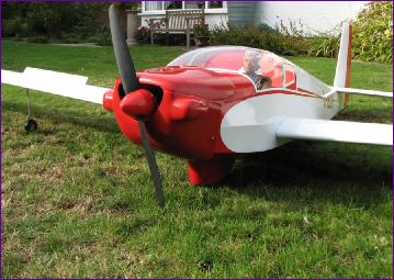
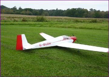
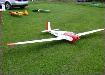
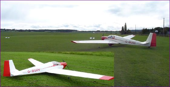
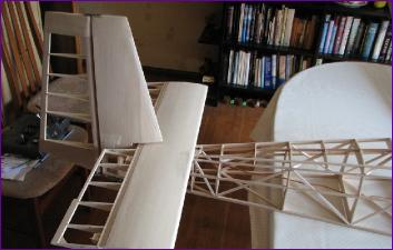
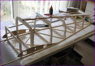 At this stage, I couldn't resist plugging the wings on to see how it looked.
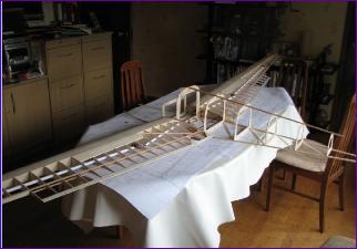 'Big' was the answer!
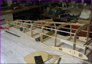 Once the vertical diagonals (?!) were in place, the root ribs could be fitted permanently, securing the main joiner box and incidence keeper tube in the process.
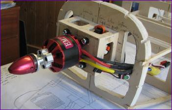
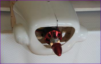
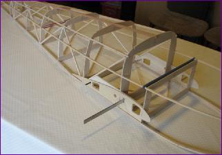 I did steam bend the basswood longerons to roughly the right shape before fitting them, so it was now time to fit the front two formers. Rather than move F1 forwards and re-calculate its shape, I positioned it as per plan and set about making a mounting box to support the motor.
|
||||||||||||||||||

|
||||||||||||||||||
|
||||||||||||
September 2010 (more on September)
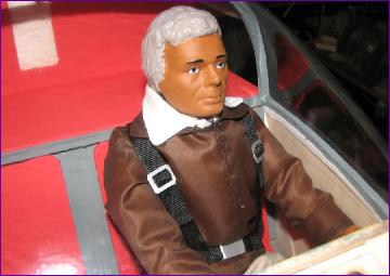
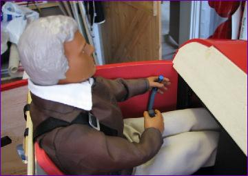
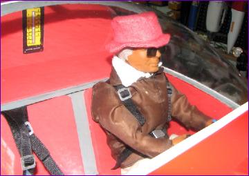
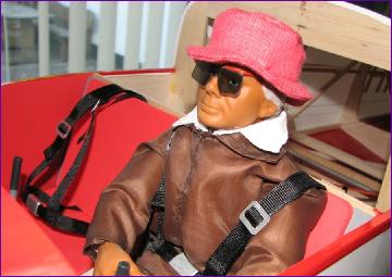
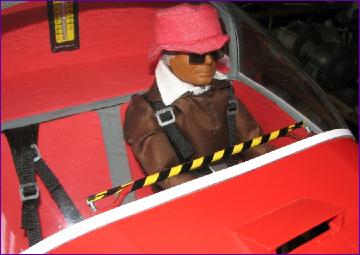
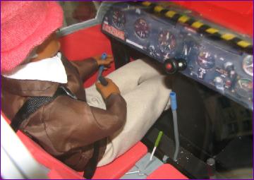
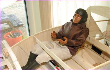
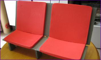
I also made the basic seat bench at this point so that the pilot could be properly positioned. |
||||||||||||
|
||||||||||||
|
||||||||||||
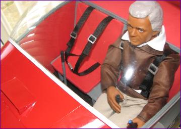
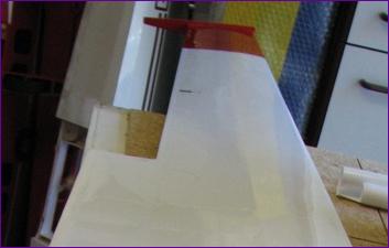
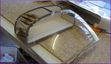
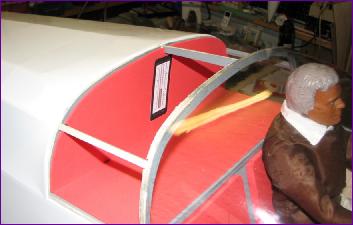
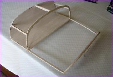 The first task of the month was the construction of the canopy frame. After a lot of deliberation about ease of access, both for rigging the model and for battery changing, I decided to build the rear glazed section of the cabin onto the removeable canopy. This rules out the possibility of front-hinging the canopy as per the full size but, since the frame was a pretty fragile affair, I had already abandoned that idea anyway. The upside is that the connecting of the wing servo extension leads and fitting of the wing-retaining elastic bands should be a lot easier.
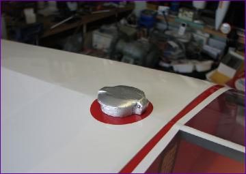
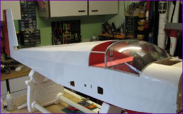
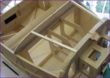 There was also much head-scratching about access to the battery position in the pilot's footwell. I did consider amputation but then spent quite a while trying to work out a way of fitting the battery through the passenger footwell under the pilot's feet. The breakthrough came when I spotted the air vent which sits on the top of the nose between the front of the canopy and the back edge of the cowl and realised that, by making this as a hatch, the battery could be dropped in vertically - with the added bonus that it keeps open the option of adding a passenger later - without the need for amputation. What's more, the canopy doesn't have to be removed for battery access.
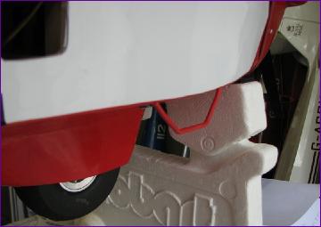
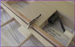
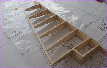
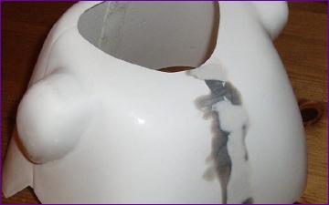
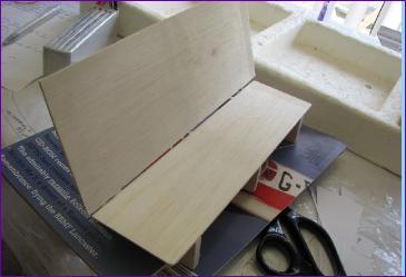 The picture shows the partially built battery box, which is screwed in place. It will need some internal guide rails added later but for the moment there is still some leeway in the precise positioning of the battery.
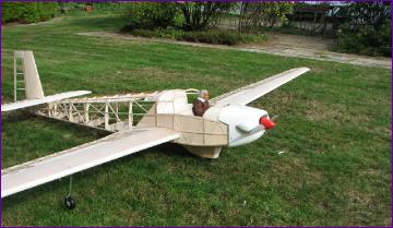
|
||||||||||||||||||||||||||||||||||||||||||||||||||||